Atari Area 51 Site 4 Video Arcade
Repairs, Restorations, Tweaks and Insights

Introduction
Original 11/2/2013
Updated N/A
I started looking for a shooter game back in around January 2013. I was looking for one of the various Time Crisis games, one of the House of the Dead games, or even a Carnevil. Not much was showing up locally and months passed with no success. Out of the blue, a local collector got hold of several project games and one of them was a project Area 51 Site 4. I had never played Area 51 Site 4 but the price was reasonable so I decided to take it home and get it working.
Initial Triage
Original 11/2/2013
Updated N/A
When I brought Area 51 Site 4 home, I did a quick triage to see what obvious problems it had. I discovered the following:
-
As was explained to me before purchasing, the left gun did nothing (gun trigger had no effect and game wouldn't track the gun)
-
Similar to above, the right gun didn't work correctly. While the trigger did function, but the game still wouldn't track its movement
-
The CPU fan was making a terrible noise and was starting and stopping
-
A previous owner had done some poor electrical work on the left gun wiring. It was now effectively hard wired into the cabinet.
I did some research regarding Area 51 Site 4 and broken light guns as well as light gun games in general. I found something that was a little concerning. Area 51 Site 4 has a custom chip that is known to break and this chip is involved in making the guns work. I wondered whether this was the reason that both guns didn't work? Repairing the custom chip runs around $200 dollars, so it's not really sensible. Hopeful that the problem (or problems) didn't involve this chip, I started looking at other possibilities.
Checking and Adjusting the Voltage
Original 11/2/2013
Updated N/A
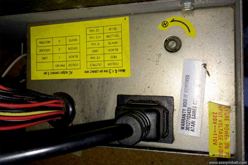
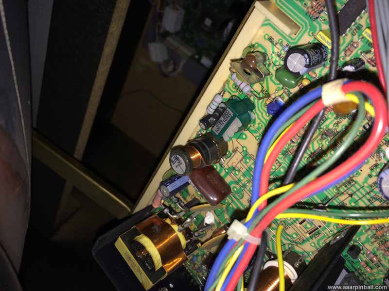
The first task I did was to check the voltage coming from the power supply. The game should receive +5V, +12V and -5V. At first I measured these without the PSU connected to the main board and got back invalid readings. For this type of PSU, you must measure it under load. When measured correctly, the 12V looked good, but the +5 was high. I was getting about 5.6V. This was worrisome because I had read that the custom chip on the JAMMIT board could easily break if the 5V supplied was too high.
The PSU in the Area 51 Site 4 game has a little potentiometer that allows the 5V to be adjusted. I turned the dial and got the voltage to be just a little over 5V. I also measured the +5v on the left gun's 5v connector to make sure it stayed at a reasonable value further into the circuit. The voltage looked good at the gun also.
The PSU is shown below. The pot at the upper left with the arc and a "circle h" is where the 5V adjustment can be made.
With the voltage adjusted, I tested the guns again. They behaved exactly as before --- no improvement. I didn't expect the left gun to work since I could see a wiring problem, but I thought the right gun might have started working. I started looking closer at the individual guns.
Repairing the Left Gun
Original 11/2/2013
Updated 11/7/2013
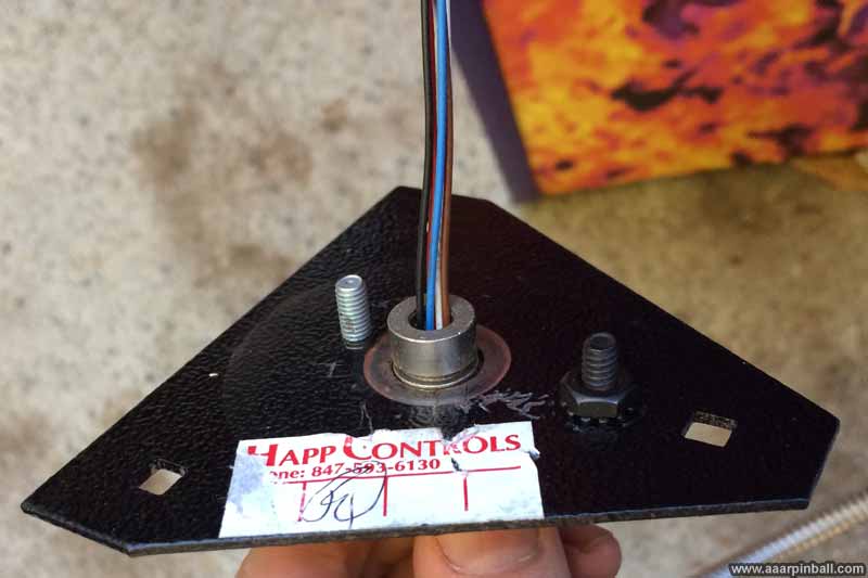
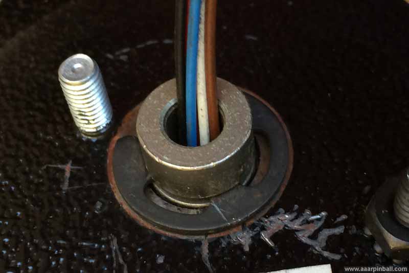
When I was performing triage, I quickly found something that surprised me. The left gun had been "permanently" connected to the cabinet. Someone had used crimp type connectors and permanently attached the gun to the cabinet wires. I also noticed that one of the wires had been pulled out the of the crimp housing. This is shown below.
Here is how the Atari Area 51 Site 4 guns should be wired:
-
A connector is attached the to JAMMIT board. There are two connectors on the JAMMIT board, one for each gun.
-
This connector goes from the JAMMIT board into the front of the cabinet, where it terminates as a 2x6 pin female Molex.
-
A male 2x6 pin Molex then adapts the connector down to a small connector.(*see note below)
-
The gun itself has wires with a matching small connector. This small connector is smaller than the hole in the front cabinet where the gun enters from the outside. This allows the gun to be replaced.
*note: I use the term "small connector" because I believe the original Atari guns may have used 5 wires while replacement Happ guns use a 4 wire connector.
Because the "small connector" didn't exist and the player 1 gun had been permanently attached to the male 2x6 Molex, the gun couldn't be removed from the cabinet. Technically you could disconnect the gun because you could disconnect the two 2x6 Molex connectors, but the 2x6 Molex connector was larger than the hole in the front of the cabinet, so the gun couldn't be removed.
Recall that one of the wires had broken off the "permanent" crimping. Could this be the reason the left gun wasn't working? Unfortunately no, but it was a step in the right direction. I temporarily connected the broken wire and found the left gun would now react when the trigger was pulled, but still would not track anything on the screen. At this point the left and right guns were behaving the same, at least.
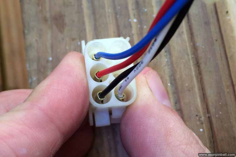
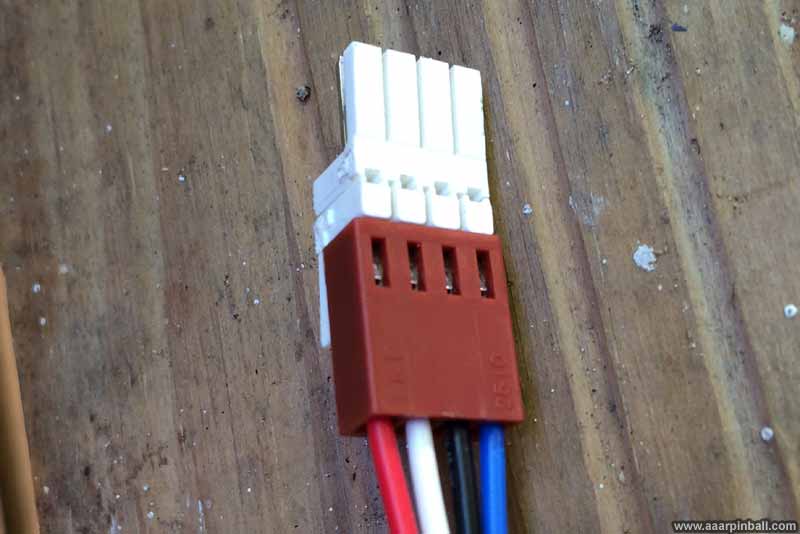
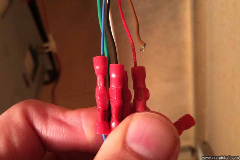
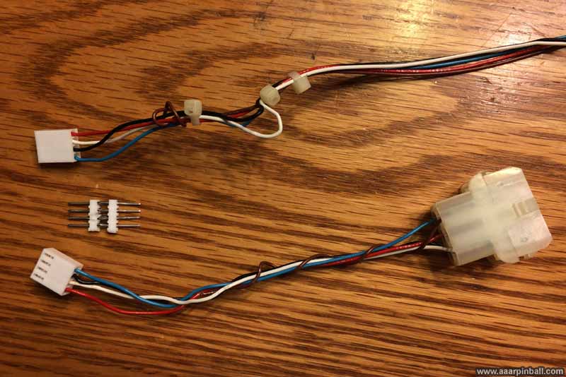
I didn't like the fact that the left gun was hard wired, so I decided to connect it properly. I cut the wires, pulled the wires out from the cabinet and attached a small 4 pin connector to the gun's wiring. I also attached the same 4 pin connector to the wires that attach to the 2x6 Molex inside the cabinet. I modeled this after how the right gun was connected. There was one difference. The 2x6 Molex for the right gun had 4 wires while the 2x6 Molex for the left gun had 5 wires. At this point, I simply didn't connect the extra (brown) wire when building the connectors. The resulting connectors are shown below. The cable on the top goes to the light gun and the cable at the bottom connects to the 2x6 Molex coming from the Area 51 Site 4 JAMMIT board. The ugly thing in the middle is used to connect the two 4-pin connectors together. I really should use a "z-connector" but I wasn't able to find one, so I made this instead.
When I connected everything together, I was disappointed to find the left gun would no longer register the trigger. This was a step backward as this functionality was previously working once I temporarily connected the broken wire. I immediately thought it was probably related to the brown wire that wasn't connected. In retrospect, it was pretty obvious the player 1 gun's trigger wouldn't work because this same failure occurred when I originally noticed a wire was broken --- and it was the brown wire that I didn't connect while adding the proper connectors.
The question was, "why did the player 1 gun need 5 wires and the player 2 gun only needed 4 wires?" After some investigation I found out there are different revisions of the guns. The original Atari Area 51 Site 4 guns used 5 wires while HAPP .45 replacement guns only used 4 wires. It turned out that my player 1 gun was an original and my player 2 gun was a Happ .45.
After looking at the wiring diagram and schematic for the original Atari gun, I found that both the brown and black wires connect to ground. Knowing this, the solution turned out to be simple. On the gun side of the wiring, I connected the brown wire to the black wire at the 4-pin connector. Now the player 1 gun would register the trigger. This is not shown in the picture above.
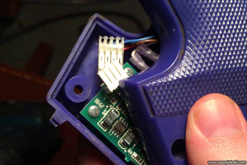
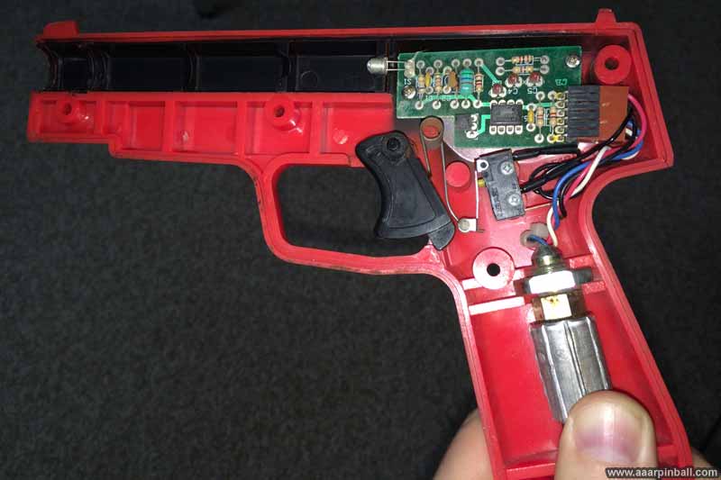
With the trigger problem solved and the wiring fixed, I started looking further into why the game wouldn't track the gun's movement. I opened up the player 1 gun and immediately saw a problem. The connector for the PCB with the photodiode wasn't attached! This is shown below.
I attached the connector properly and put the gun back together. And it worked! My Atari Area 51 Site 4 now had a working player 1 gun. After running the calibration function, the game accurately showed a "bullet" when the gun was aimed when the trigger was pulled. Area 51 Site 4 was now playable!
Repairing the Right Gun
Original 11/2/2013
Updated 11/7/2013
The right gun's trigger would register but the game wouldn't track where the gun was aiming. Since I had found the left gun's wiring wasn't attached correctly inside the left gun, I decided to check the inside of the right gun. After opening up the right gun, I found nothing wrong. I had read that the PCB inside the gun sometimes goes bad (often the phototransistor itself on the PCB goes bad),. After checking the various connections and ensuring nothing needed solder reflowing, I decided to order a new one.
The part arrived a few days later. I opened up the gun, swapped the PCBs, and tested it out. There was no change in behavior.
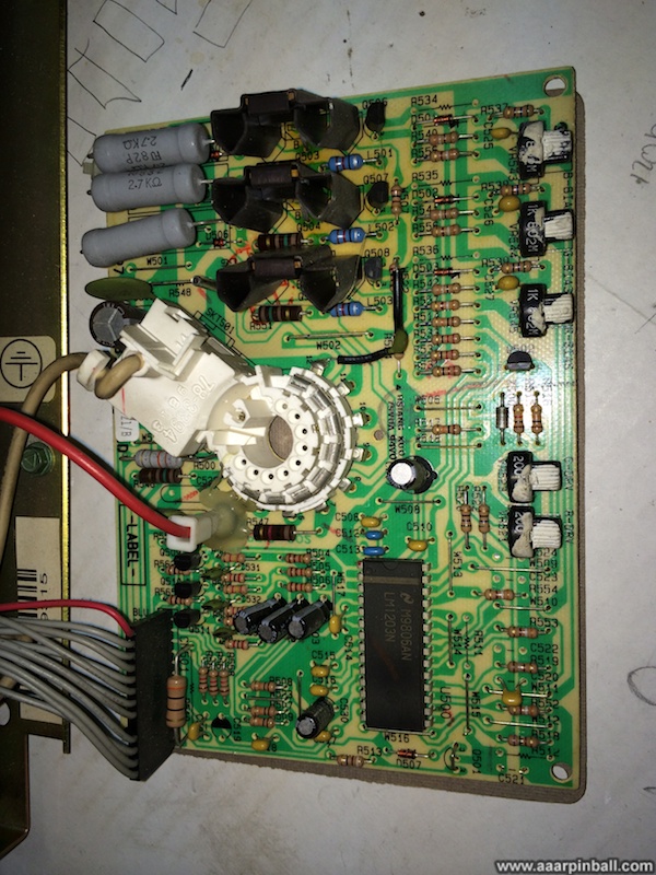
Just trying out some variations to see what happened, I connected the right gun into the left gun's connector on the JAMMIT board. The gun still didn't work. I then connected the left gun, which was working correctly, into the right gun connector on the JAMMIT board. It no longer worked! This was a strong indication that something was wrong with the JAMMIT board, specifically with the logic that supports the right gun. I again thought about that expensive custom chip and wondered whether it had been damaged when the voltage was set too high.
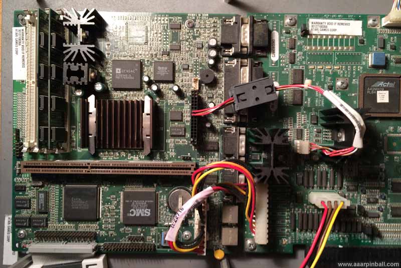
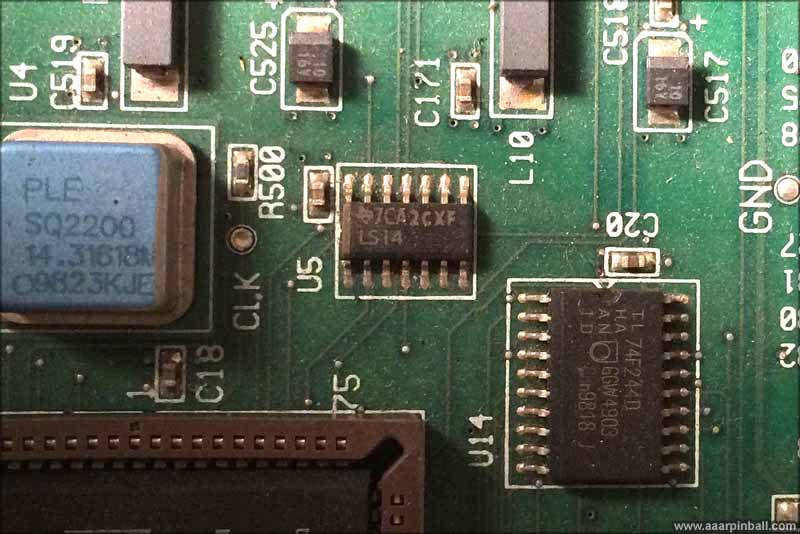
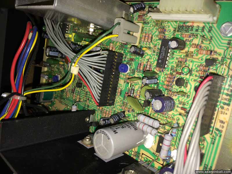
Looking further into gun repairs, I learned that most light gun games have the gun's sensor output go through a 7414 chip before the signal enters the custom ASIC. This is an inverter with Schmitt Trigger inputs. At a high level, this chip invests the signal (low becomes high, high becomes low) but it also ensures the output is very stable and quickly transitions from low to high (or high to low). I looked closely at the JAMMIT board and found an LS14 chip, so the JAMMIT does send the gun's signal through a 7414 before it goes to the custom chip. A picture is shown below.
The 7414 chips were pretty inexpensive (less than a dollar), so I proactively ordered a couple. However, before they arrived a found the real culprit for why the right gun wasn't working.
I decided to go back to "square one" and check the voltage on the JAMMIT board's right gun connector. When I first got my Area 51 Site 4 game, I checked the gun voltage when adjusting the 5V pot. However, I only checked the voltage for the left gun. I had not checked the voltage for the right run. When I checked for 5V on the right gun connector I found there wasn't any! Now I knew why the "working" left gun wouldn't work when connected to the right gun connector. It wasn't getting any power. I was happy to find this because it offered the possibility that nothing was wrong with the 7414 and nothing was wrong with the custom ASIC.
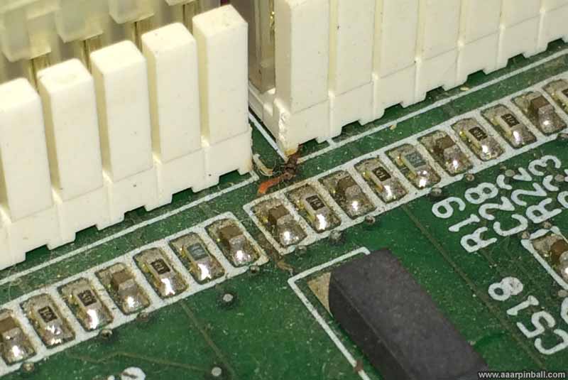
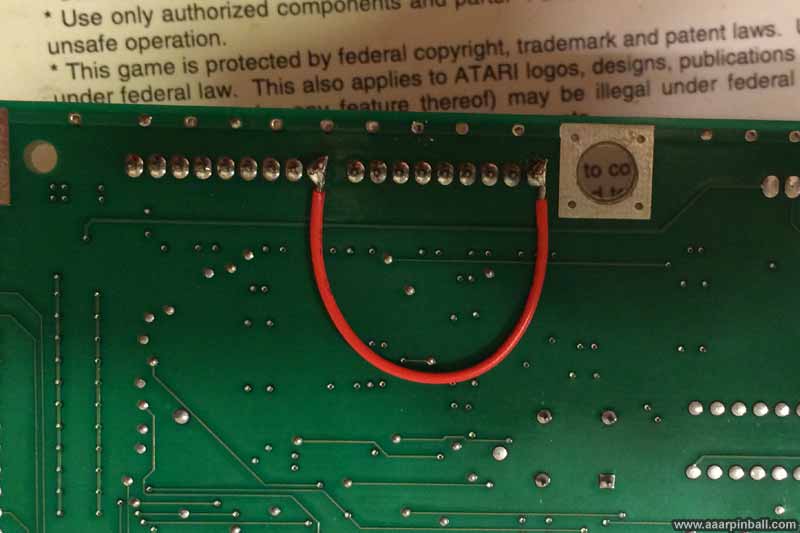
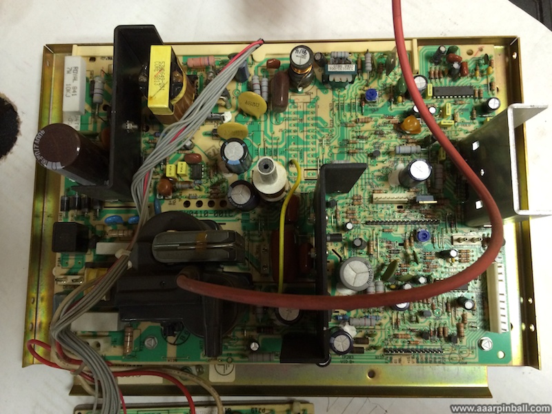
I took the JAMMIT board out of the game a looked at it closely. It wasn't very obvious, but when looking closely I could see that the trace for the 5V going to the right gun had been blown. The picture below shows this blown trace. It's a little hard to see, but it's directly in the center of the picture.
Atari didn't provide a schematic for the JAMMIT board, so I had to use my digital volt meter and try to recreate the circuit that feeds the 5v. After "ohming" out various connectors and pins, it became clear that the 5v feeding the right gun should be exactly the same 5v that was feeding left gun. While this wasn't too surprising, one never knows what sort additional electronics are tied into a line, such as caps and so on,
I decided the easiest way to repair this broken trace was to install a jumper on the bottom of the JAMMIT board between the left gun's 5v pin and the right gun's 5v pin. This was a simple task and the result is shown below.
I put everything back together, powered on the game, and started by testing the (previously working) left gun. It was still operating as expected. I then tested out the right gun... and it was working! After a quick calibration, the right gun was now accurately tracking and registering the trigger. Now Atari's Area 51 Site 4 could be played by two players!
CPU Fan Noise
Original 11/2/2013
Updated N/A
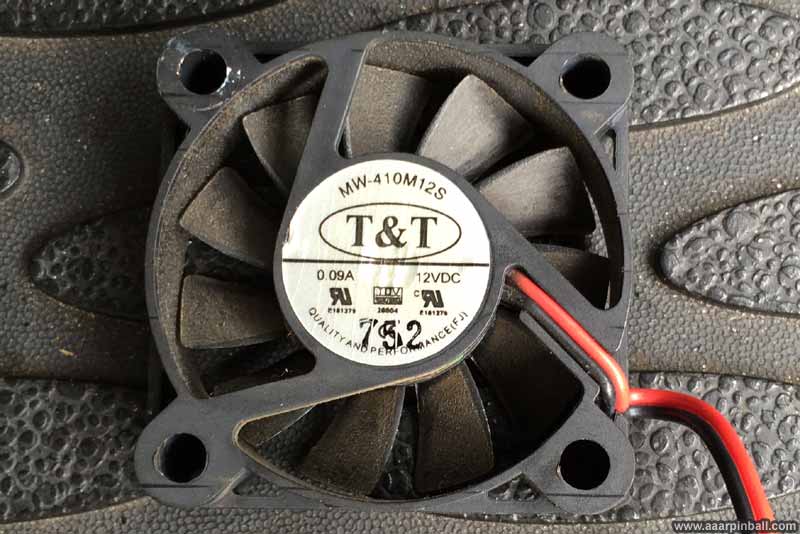
The CPU fan was making a terrible noise. In addition to noise, it was cycling between spinning and not spinning. I didn't want the CPU to overheat, so I looked into what I could do to get the fan working better. The stack fan is a T&T MW-410M12S, which is a 40mm x 40mm x 10mm fan that uses 12V DC. It is pictured below.
I wondered if there was any place to add "3-in-1" oil, so I pulled off the label and found an exposed area that (perhaps?) could benefit from oil. This is shown below.
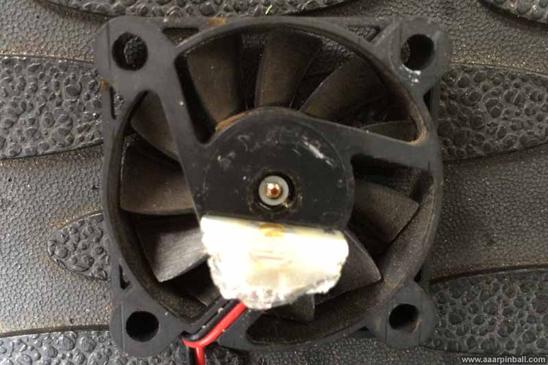
I added a single drop of "3-in-1" oil to this exposed area. After reconnecting the fan, it worked like a champ. It was silent and spinning like crazy.
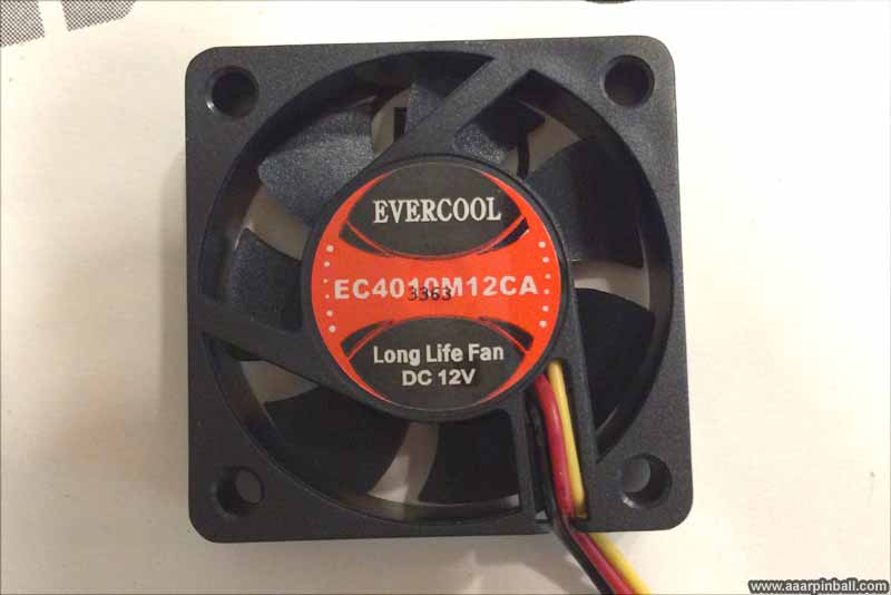
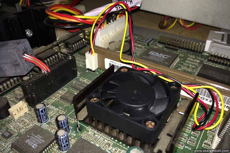
While the "repaired" fan seemed to be working great, I got some feedback that this may not be a long term solution. Since I didn't want to mess around with the fan stopping (and perhaps doing so in a manner where I didn't notice, causing the CPU to overhead), I decided to purchase a new fan. The local computer stores didn't have a lot of 40mm x 40mm x 10 fans, but I did find the one below for just $6.95. A picture of the installed new fan is also below.
Silly Text on the JAMMIT PCB
Original 11/2/2013
Updated N/A
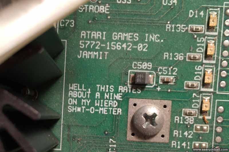
When I was looking at the JAMMIT board and trying to figure out why the guns were not working, I noticed the following text.
	ATARI GAMES INC.
	5772-15642-02
	JAMMIT

	WELL, THIS RATES
	ABOUT A NINE
	ON MY WIERD
	SH*T-O-METER
Want to see for yourself? Check out the photo below.
Hard Drive
Original 11/2/2013
Updated N/A
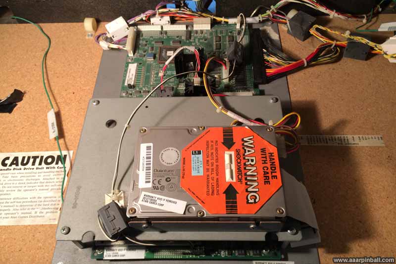
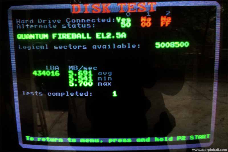
Atari's Area 51 Site 4 uses a hard drive to store the game. My game has an original hard drive, which is a Quantum Fireball EL drive. It's a 5400 RPM drive with 2.5GB of storage. The Area 51 Site 4 game has a hard drive diagnostic and checks the entire hard drive. It let it run for one complete hard drive pass and it experienced no errors. The first picture below shows the hard drive and the second picture shows the hard drive diagnostics.
Converting from a Hard Drive to a Secure Digital Flash Card
Original 11/14/2013
Updated 11/15/2013
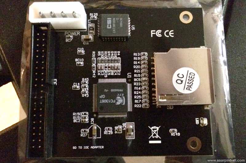
The Hard Drive in my Area 51 Site is original. It's a 2.5GB Quantum Fireball EL circa 1998. It's working great. Way to go, Quantum! But 15 years is pretty old for a Hard Drive, so I wanted to replace it with a modern flash drive. I did some research and read that while many other games from this era work well with an IDE to Compact Flash adapter, Area 51 Site 4 did not. Area 51 Site 4 did, however, seem to work with IDE to Secure Digital adapters.
I looked at Frys and Microcenter for an IDE to SD adapter but didn't find one. So I tried eBay. There were a lot of options and they were insanely cheap! I paid $3 for the SD to IDE adapter and $7 to have it shipped from Hong Hong. It arrived in about a week and a half, so no complaints there. There is no model number so I cannot tell you the specific one I purchased, but here is a picture.
To test it out quickly, I found the CHD (a hard drive image) on the web. This was the same CHD used for MAME. After downloading, I used the chdman program to write the CHD to a Secure Digital card. This took about 15 minutes or less. I went down to where my Area 51 Site 4 is, disconnected the IDE cable from the hard drive and connected it to the IDE to SD adapter. I plugged in the power cable and inserted the SD card into the adapter.
I turned on Area 51 Site 4 and ... it worked great! It booted up like normal and played just fine. I did observe two interesting artifacts:
-
My settings had changed. Apparently Area 51 Site 4 stores all settings on the hard drive. This isn't surprising, but I thought the game might have some non-volatile memory somewhere.
-
The game reported my serial number was 0. This surprised me the most because it meant (1) the serial number is somehow encoded into the hard drive image and (2) the person that made the MAME CHD for Area 51 Site 4 was aware of this and edited the serial number.
Having proven that the IDE to SD adapter worked fine, I decided to be completely legit and made a CHD of my original hard drive. I connected the Area 51 Site 4 hard drive into an on PC with IDE and used the chdman program to create an exact copy of my hard drive. It was fairly straightforward with one minor complication. The chdman program complained it couldn't determine cylinders, head and sector count because the hard drive size wasn't a multiple of 512. I looked up the Quantum Fireball EL 2.5GB hard drive and found the values are 5300, 63, 512. I added this to the chdman command line and the CHD creation worked like a champ. It did, however, take a few hours.
With an image of my original Area 51 Site 4 hard drive in hand, I then copied this to the Secure Digital card. About 15 minutes later, I was plugging the SD card into the adapter and testing the game. With an exact image of my original hard drive on the SD card, it played exactly like it did with the hard drive. My settings were immediately available and my serial number was showing again.
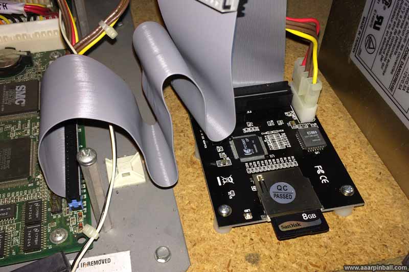
I had a spare IDE cable, so I replaced the original one (which was very short). While doing this I tried connecting the IDE to SD adapter into both the inner connector on the cable and the outside connector. Both worked just fine. I'm sticking with the outer connector because it allows the IDE to SD adapter to be placed further away.
Below is a picture of the IDe to SD adapter with an IDE cable and power connected.
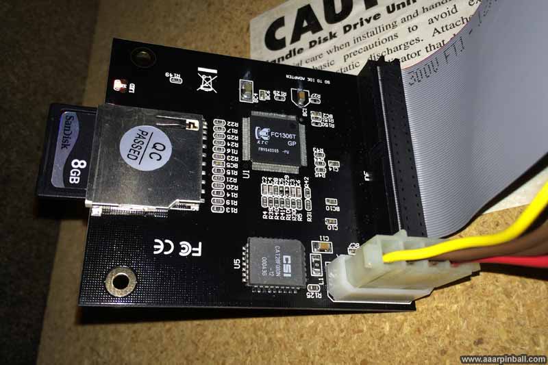
To make this setup more professional looking, I purchased 4 nylon spacers and mounted the IDE to SD adapter on top. I didn't realize until I went to mount the adapter that it only had 2 mounting holes. These holes are on the side where the SD card is inserted. I proceeded normally with the spacers for these mounting holes. For the remaining two mounts, I simply gorilla glued the spacer to the platform and the SD card simply sits on the spacers. See below for a picture.
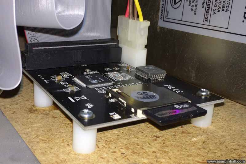
A somewhat larger point-of-view of the IDE to SD adapter for Area 51 Site 4 is shown below.
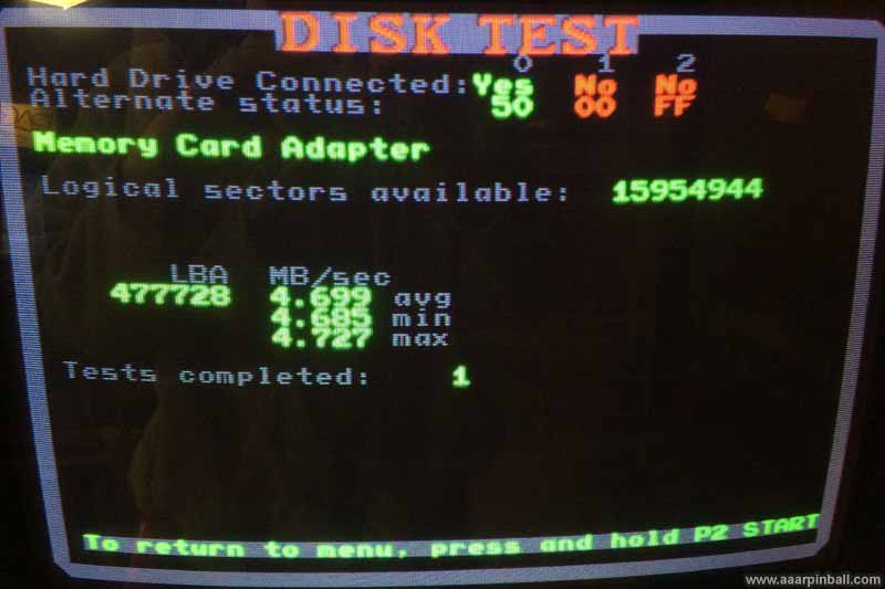
I ran an entire cycle of the "Disk Test" and found no error. I was surprised to see the data rate is about 1 MB/s slower than the 15 year old hard drive. I haven't noticed this causing any trouble, however.
Gross Speaker
Original 11/7/2013
Updated N/A
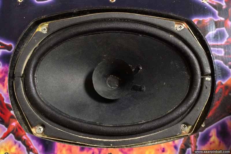
The dedicated Area 51 Site 4 game uses a single speaker for mono sound. This speaker is placed directly in the center of the control panel. It is covered with a grill, but the grill doesn't prevent liquid from flowing onto the speaker. In the past, my Area 51 Site 4 seems have have had something spill on this grill. The results are gross looking and a picture is below.
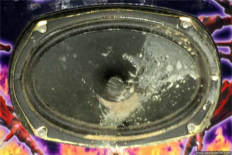
I used a highly diluted mixture of "Simple Green" and water to clean the gunk off. I got about 90% of the gunk off using a damp cloth. The remaining 10% was thick. I got it damp and (very gently) used the side of a toothpick to scrape off the gunk. I never pushed down onto the speaker. Rather, I scraped bath and forth. It cleaned up very well! The picture below shows the final result.
Fixing Up the Control Panel
Original 11/5/2013
Updated N/A
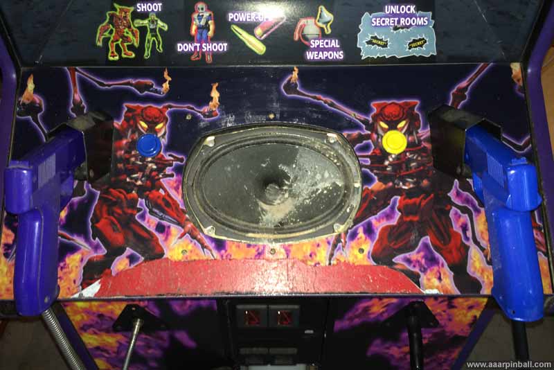
The Area 51 Site 4 control panel was in good shape except for a 1.5" area toward the bottom. The artwork had been chipped off and a previous owner had painted it red. My guess is that the control panel eventually chipped away as a result of guns hitting it over the years. A picture of the control panel is shown below. Note: The grill has been removed from the speaker and you can see some discoloration. I think this is the result of a spill that occurred sometime in the past.
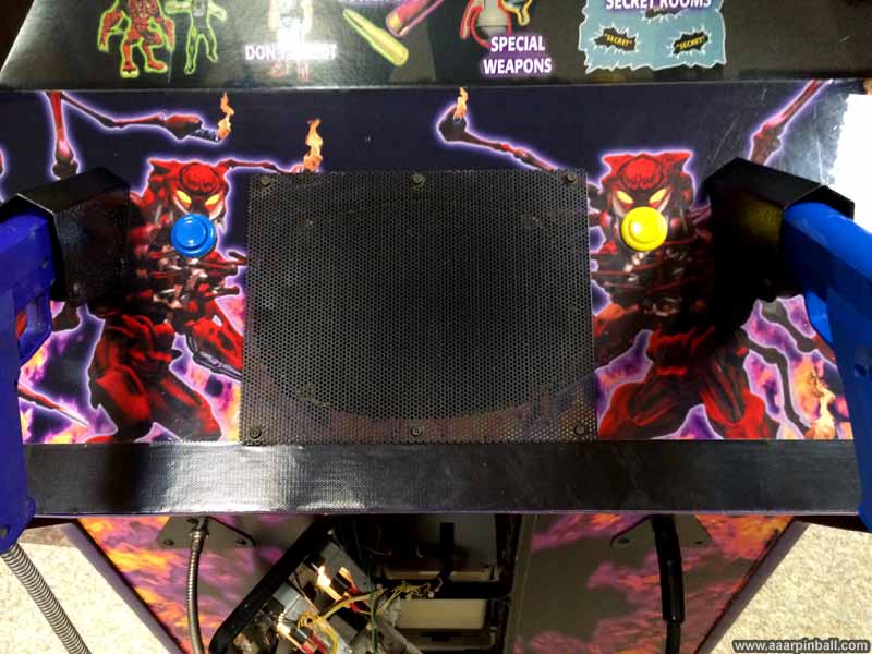
I decided to cut off the bottom of the control panel's artwork and replace it with high quality gorilla tape (black). The result looks pretty good, especially considering the cost of the repair.
Monitor Adjustment / Cap Kit
Original 11/2/2013
Updated 2/24/2014
The monitor on my Area 51 Site 4 always looked very good. One aspect has stood out: the focus. It's as sharp as I believe it can get.
While the picture looked pretty good, I found that the blacks were being crushed a little. Using the color brightness test pattern, I adjusted the "screen" setting on the flyback and adjusted the contrast and brightness near the coin door. The image looked excellent.
After having Site 4 for a couple of weeks, I noticed two problems. First, the monitor would very infrequently shut down. This happened, probably, around 4 times over a couple months. The game would keep playing but nothing was displayed. Power cycling the game would cause the monitor to start working again. The second problem was that the width of the image would change a little bit. It's a 25" monitor and the width would increase or decrease about 1/4" on each side.
I decided a cap kit was the appropriate next step. A cap kit is a way of saying "replace all the capacitors on the monitor board". The caps used in many of these monitors were not always the highest quality. Plus, the games were left running for long periods of time so the caps got a lot of use. It's extremely common for a cap kit to solve whatever problems a monitor may have. I got introduced to monitor work on my Asteroids Deluxe, but I had not done a cap kit before. Unfortunately, the Site 4 game uses a Well Gardner k4700 which has one of the largest number of capacitors. There are a little over 40 caps that needed replacing.
Performing a cap kit involves the following:
-
Removing the back cover
-
Discharging the monitor
-
Removing the anode from the monitor
-
Removing the screws that hold the monitor board in place
-
Removing all the cables connected to the monitor board
-
Removing the neck board of the monitor
-
Pulling the boards out of the game
-
Individually removing the caps and installing new ones. I did this one at a time: desolder old, install new, repeat. The cap kit I got contained a printout with all the caps. I marked off each one after completing.
-
Putting it all back together
-
Testing!
It's still a little early to tell, but both problems (width changing and monitor shutdown) seem to have gone away.
Some pictures of the monitor board are shown below. There isn't much to show regarding a cap kit... one removes the old caps and installs the new ones. These are before pictures showing some caps. I don't have any after pictures.
Improving Gun Accuracy
Original 3/1/2014
Updated N/A
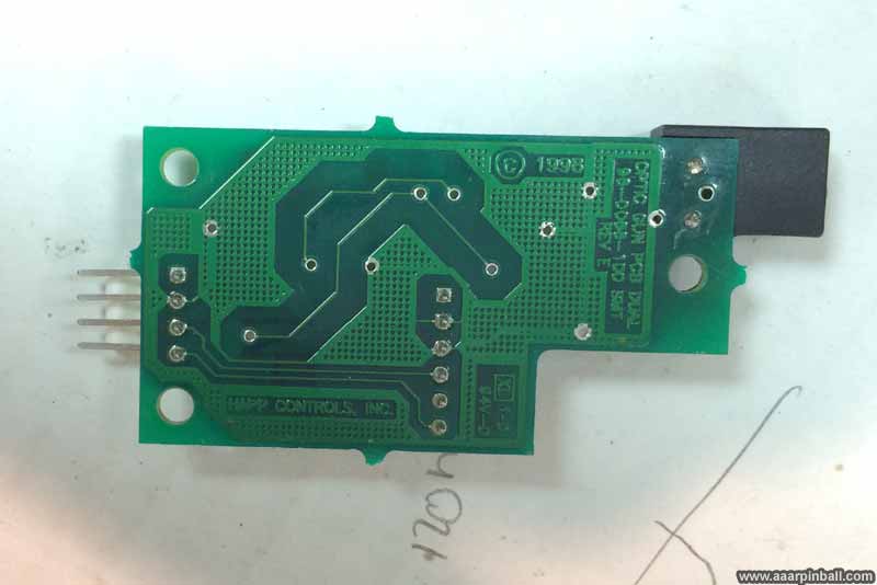
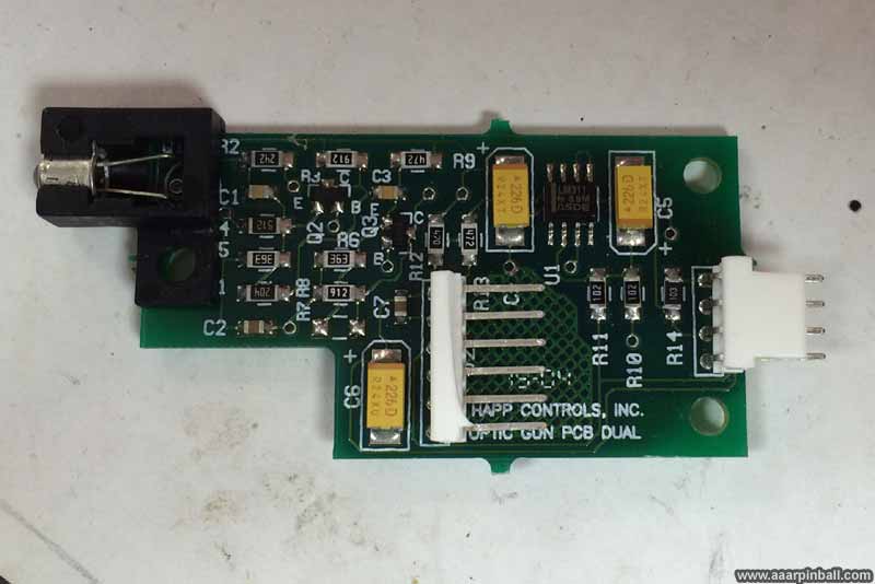
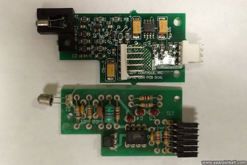
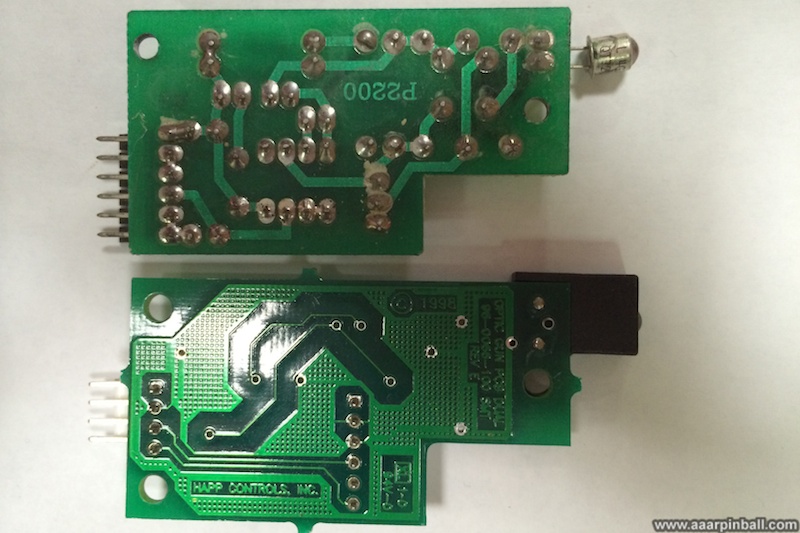
While the player 1 gun worked, it wasn't as accurate as the player 2 gun (even after calibration). The gun would track accurately for the middle of the screen, but would get noticeably off as the tracking approached the corners. It turns out that the PCB inside the player 1 gun was a much older generation than inside the player 2 gun. I replaced the older PCB with a newer one and the tracking is now spot on.
Below is a picture of the newer PCB and the older PCB. As you can probably tell, the newer PCB is on the top and the older PCB is on the bottom.
Defeating the Alien Queen
Original 3/1/2014
Updated N/A
The strategy is pretty simple:
1) Collect all the power ups you can
1a) Get several in the mini games
1b) Get all you can while playing the main game
2) Save your power ups for the very end of the game
2a) This will cost you lots of quarters because you are basically saying "I'd
rather die than use a power up"
2b) Or, if using free play, it's rather cheap
2c) Be careful when looking aliens near the bottom of the screen. It's not hard
to accidentally launch one of your special wraps!
3) When you encounter the alien prior to the final battle, crazy shoot its head
3a) Use the "manual rapid fire" approach where you hold the gun in your non-dominant
hand and then use your index finger on your dominant hand to rapidly pull and
release the trigger
3b) You can get him 10% or a little more down in health
4) In the final battle, always use the "manual rapid fire" approach
4a) Use your special weapons as quickly as you can, but NEVER when the alien's
glowing head is visible
4b) When the glowing head is visible, shoot it like crazy using the "manual
rapid fire"
4c) When you run out of power ups, shot the flaming arms and "missiles" until
the alien shows its ugly glowing head (then shot only at it)
4d) Cross your fingers you kill it before the timer runs out
When you "win" you get a little victory animation... some patriotic jets fly over and you are asked to join STAARS (Special tactical Advanced Alien Response).
Below is a video showing the final battle.
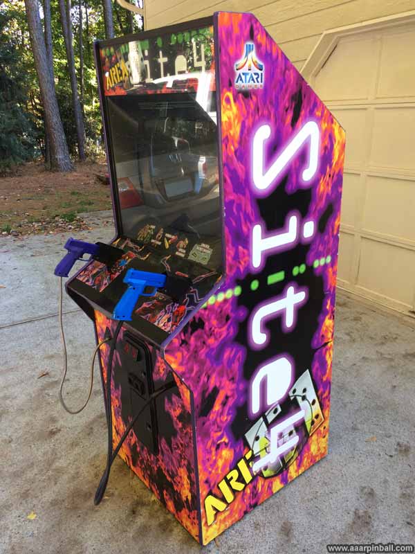
Area 51 Site 4 Cabinet
Original 11/2/202013
Updated 2/24/2014
Looking nice!
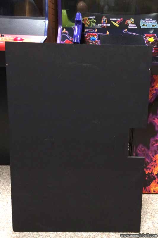
Replacement Back Door Panel
Original 11/3/202013
Updated 2/24/2014
My Area 51 Site 4 didn't come with a back door. I ended up cutting one out of MDF.
Unorganized Pictures
Original 11/2/2013
Updated N/A