Atari Marble Madness Video Arcade
Repairs, Restorations, Tweaks and Insights
Introduction
Original 11/7/2010
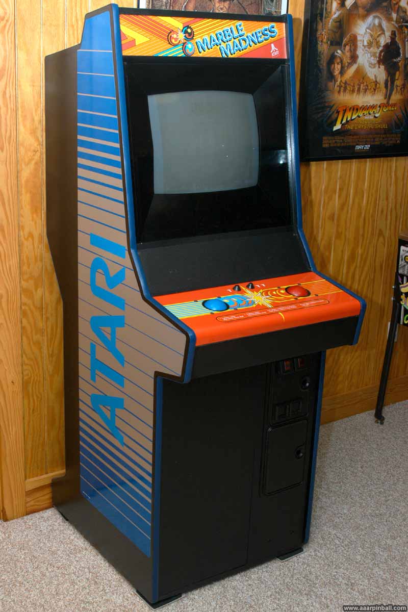
Atari's Marble Madness was one of my favorite arcade games back in the mid-80s. Back in the day, I was able to play the game for a quarter and even win the game! I'm not particularly interested in adding a lot of vids to my game room. However, Marble Madness falls into the small group of "grails" I'd like to have. I'm happy to say that I now have one.
I found that acquiring a Marble Madness takes a lot of searching. I attribute this to two causes. First, most people that have one seem to have no interest in parting with it. Second, since it is a System 1 game and can be converted into other System 1 games, it seems many Marble Madness vids were converted.
Marble Madness is unique in many ways. I've listed a few below.
-
It is the first Atari System 1 game
-
You can win/complete the game! If you were able to finish the last level, the game ends. It doesn't start again at the beginning.
-
Great stereo music. Very impressive for the mid-80s. The music still sounds good today.
-
Fun and unique gameplay (you are a marble!) with perfect control (using a track-ball)
-
For a mid-80's game, it has great graphics.
Software Exception Error
February 8, 2020
After moving Marble Madness up an down stairs, loading it in and out of a truck, driving it 30 miles, and having it sit unused for several months, it developed a "Software Exception Error". At first this problem was very rare. Over the period of a few months, the exception started occurring more frequently. It got to the point where it would, more often than not, occur after the game was powered on for 15 minutes or so.
Note: My debugging of this problem was perhaps one of my least structured efforts and this lack of structure made resolving the issue harder than it needed to be. I'm sharing my mistake because, well, we all make mistakes. Maybe reading this will help someone know what not to do. Going down the wrong path did, however, cause me to learn something interesting about System 1 games and the color palette.
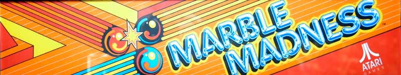
Marble Madness's behavior when the Software Exception Error occurred was inconsistent but typically resulted in a "bong" sound, the game displaying "Software Exception Error" in the center of the screen, and the graphics getting messed up. Below is a picture showing an instance of the "Software Exception Error".
When I got my Marble Madness, I wanted to have a spare System 1 main board. Recall that Marble Madness is a System 1 game and all System 1 games utilize both a System 1 main board and a cartridge board. The main board is the same across different System 1 games and the cartridge board provides the unique game. (I'm painting with a broad brush here... there are unique variants of the System 1 main board). The 2nd System 1 main board was purchased on eBay as "non-working". It turned out to have an audio issue, but I was able to fix that as documented separately on this site.
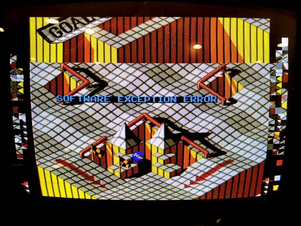
To debug the "Software Exception Error" I did two things. First, I re-seated some of the socketed chips on the cartridge board. Second, I removed the original System 1 main board and connected the cartridge to the backup main board. The results were unexpected. The Software Exception Error went away but the colors were wrong! The image below shows the bridge is the wrong color, the Marble Muncher is the wrong color, and the evil "black" marble is the wrong color.
I was being too informal when I was debugging this problem. I never should have changed two things at once (re-seating chips on the cartridge and swapping the main board).
Because the Software Exception Error went away with the 2nd System 1 main board, I spent some time incorrectly believing the issue was with the first System 1 main board and the replacement System 1 main board had it's own unique problem: that it didn't display colors correctly. I was ignoring the fact that I had re-seated the chips on the cartridge board. Trying to look back, I believe I strongly wanted the problem to be on the System 1 main board because I knew that getting a new Marble Madness cartridge board was a difficult and expensive effort (if I was unable to repair it).
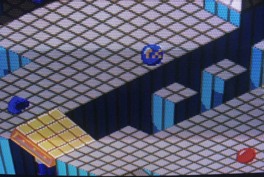
I spent a fair amount of time looking into the color problem. I found that all of the diagnostics tests showed the correct colors except for the palette test. Initially I didn't know what colors the palette test should show. I had nothing to compare it against as I couldn't find any references on the Internet. I was pretty confident my results were wrong because the first part of the test showed 8 colored objects and the colors on the first 4 were repeated on the second 4. Also, the second test showed four colored squares and the first 2 squares were colored the same as the second 2 squares.
I decided to run Marble Madness on MAME in order to get the "ground truth" for the color pallet test. Below is a picture of what my Marble Madness showed followed by what MAME displayed. Note that the quality of the first picture is not great because it's a close up of a real monitor while the second is a digital screen capture.
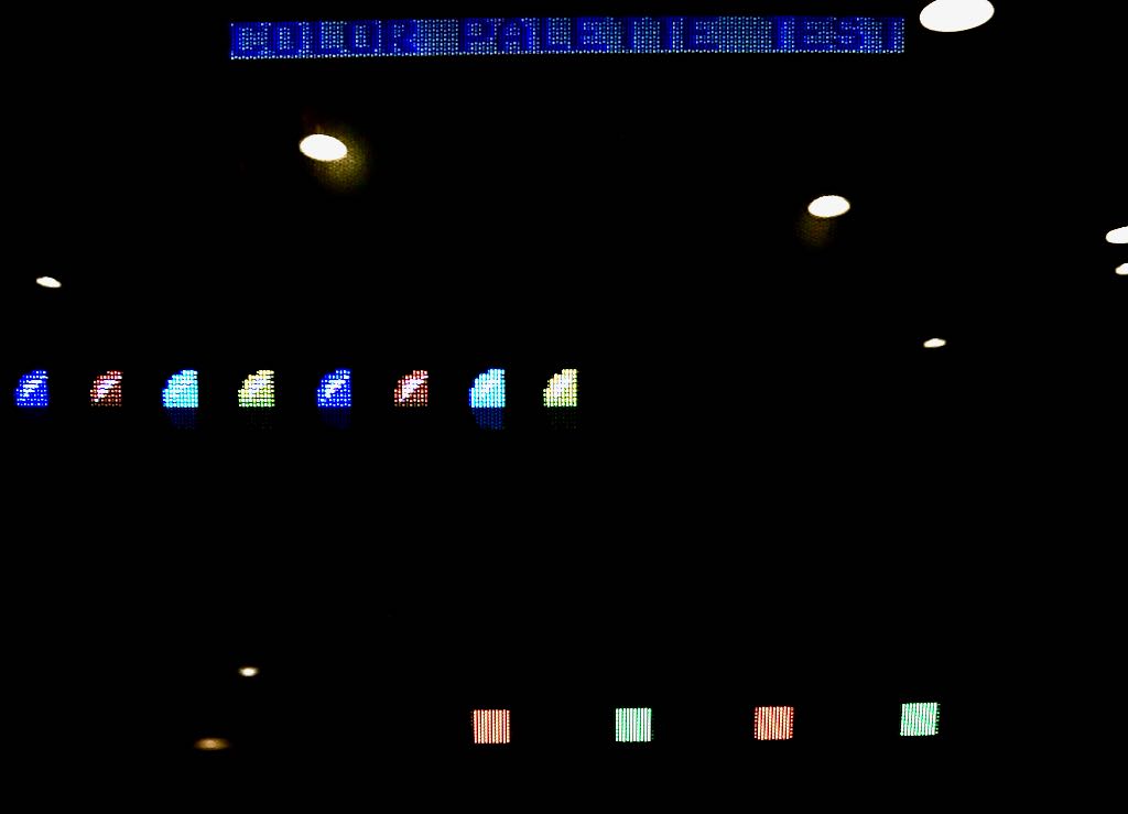
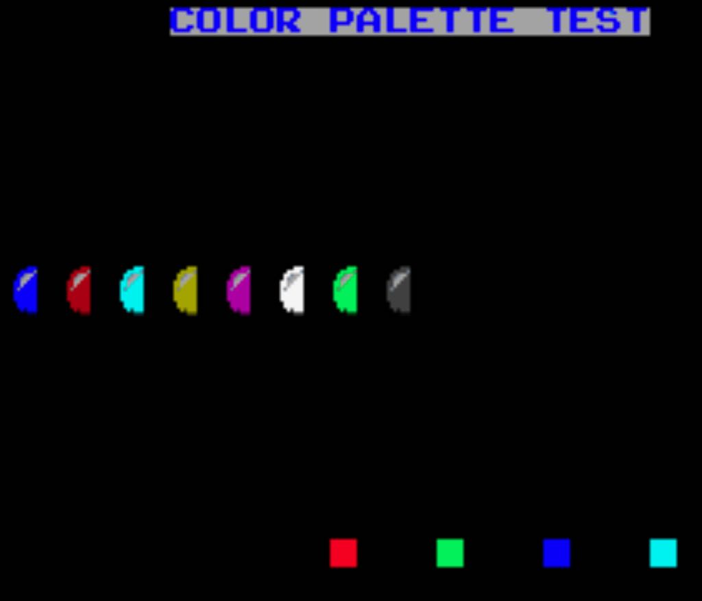
As can be seen, not only did my Marble Madness use the wrong colors, but the bottom half of the half marbles were missing too!
Now with confidence that the color palette was wrong, I started looking at the circuity involved in generating the color palette test. I found that the color palette circuity is on the cartridge board and not the System 1 main board! This was how I first realized I had gone down the wrong path and thought the main board was the problem. When I started looking into the Marble Madness cartridge, I learned that Atari made different versions of the Marble Madness cartridge. I knew there were different versions of the System 1 main board, but didn't know there was at least an original TTL design and then a more optimized LSI cartridge design. I have the LSI version but I only had schematics for the TTL version! After a little Internet digging, I found that the LSI schematics are in a document called "Marble Madness SP-276A 1st Printing".
The Graphic Palette Select circuit was rather straightforward and is shown below.
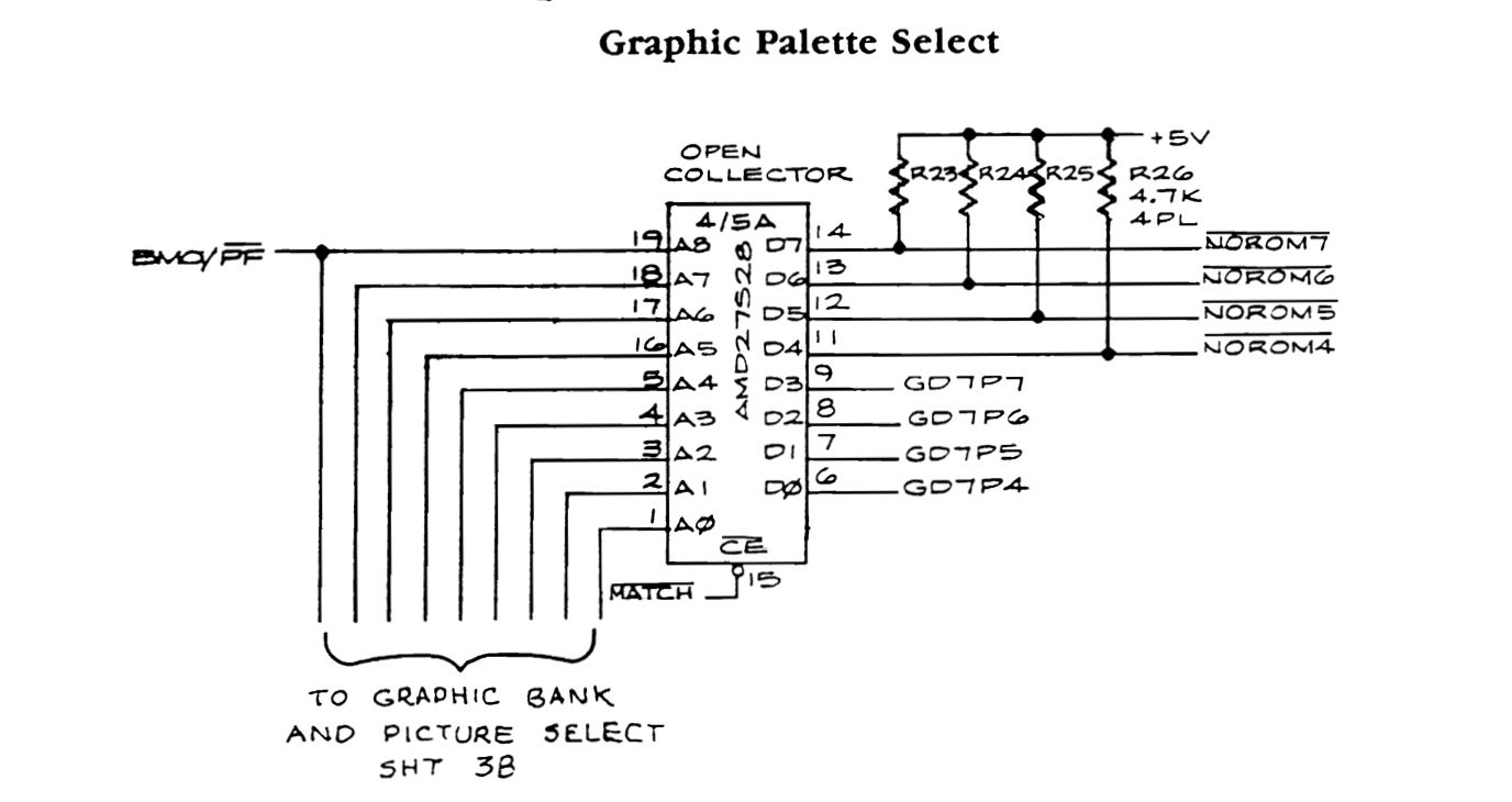
From that circuit I concluded that something might be wrong with the AMD chip at location 4/5A. I wondered if the palette select outputs GD7P6 and GD7P7 were not working or were mirroring the other outputs. This was a guess, but it was based on the fact that the displayed colors repeated.
It turned out that there was nothing wrong with the AMD chip. While looking at the GD7P7 trace and following it to the SLAG chip, I realized the mistake I had made many hours ago. When re-seating one of the SLAG chips, I put it into the unused socket at location 4E when it should have been placed into the socket at 5E! This was a rather dumb thing to have done. I was able to look at an old picture I had taken of the Marble Madness cartridge to verify I had put the SLAG in the wrong socket. Below is a picture of the INCORRECT chip placement.
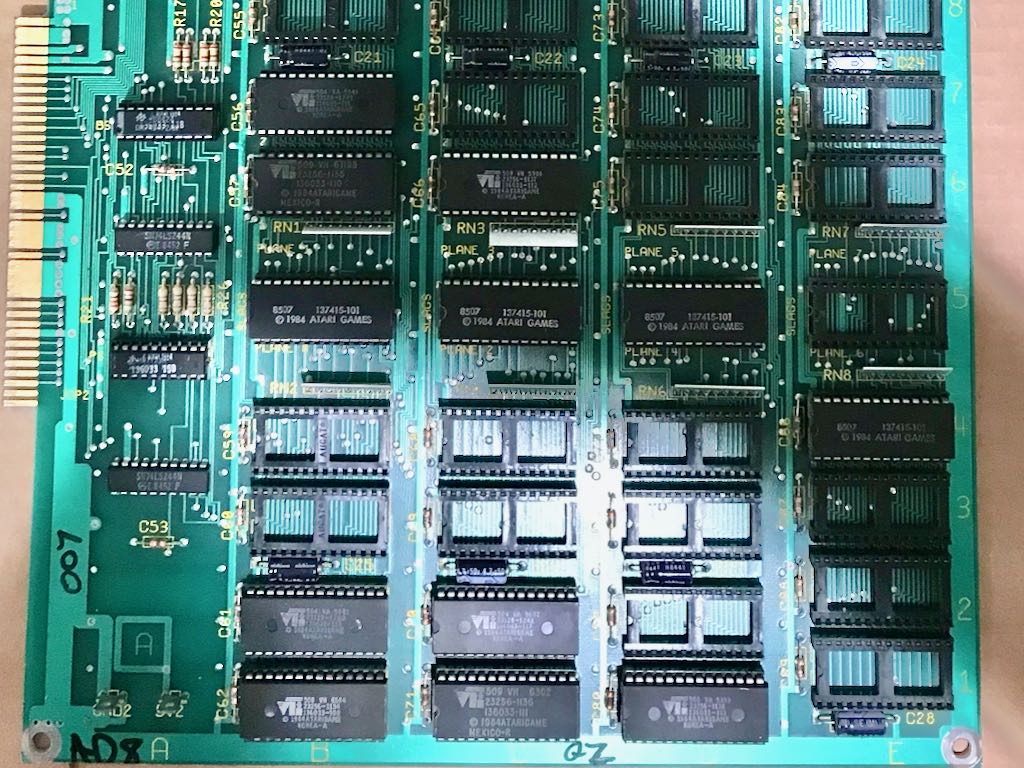
While there should be 4 chips in the center row (horizontal), the one in the rightmost column was in position 4 rather than 5. What I learned from this was that having the SLAG plane 7 chip in the wrong socket doesn't prevent Marble Madness from working, it only appears to mess up the color palette.
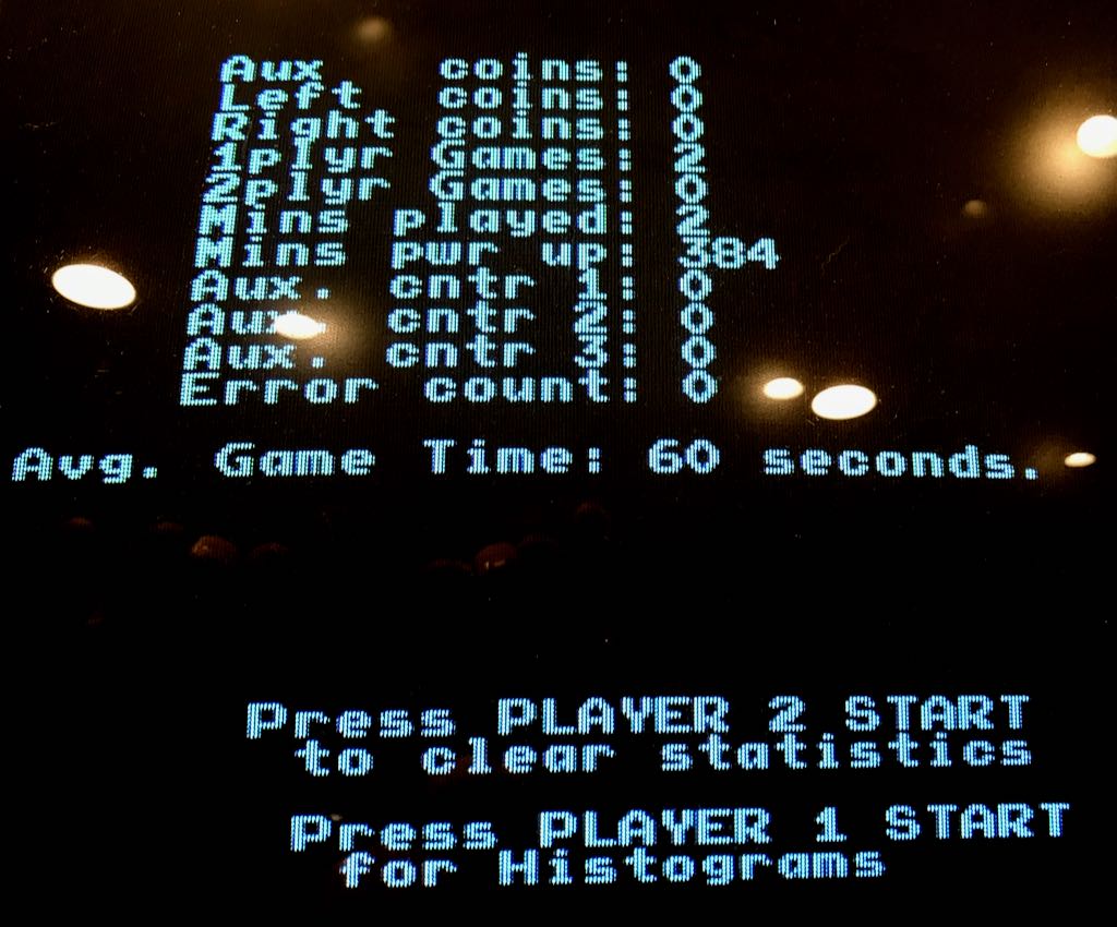
In the end, I repositioned the SLAG plane 7 chip correctly into location 5E and the game worked perfectly with the 2nd System 1 main board. I then took out the 2nd System 1 main board and replaced it with the original System 1 main board. Marble Madness continued to work perfectly. While I've tested it for even longer, the picture below shows that it ran for over 384 minutes without resetting.
The bottom line? I'm pretty confident that re-seating all the chips on the Marble Madness cartridge fixed the Software Exception Error and I went on a wild goose chase looking at the System 1 main board. But all is well that ends well, right?
Marble Madness Monitor Died
Original 7/25/2016
We had family coming to visit for the 4th of July weekend and, while I was getting the games ready for everyone, Marble Madness stopped working. It turned on, I could hear the fan, but nothing showed up on th screen. I eventually pressed the "player 1" button and the game started. Thought I could only hear it, I couldn't see it.
My Marble Madness has a Electrohome G07 19" monitor and it had died. While monitor repair isn't my favorite task, I was happy when I discovered there is a good amount of repair information available. One good source is the "G07 Flowchart" that, I believe, originated from an article written by Randy Fromm.
Below is a picture of the backside of the G07 monitor
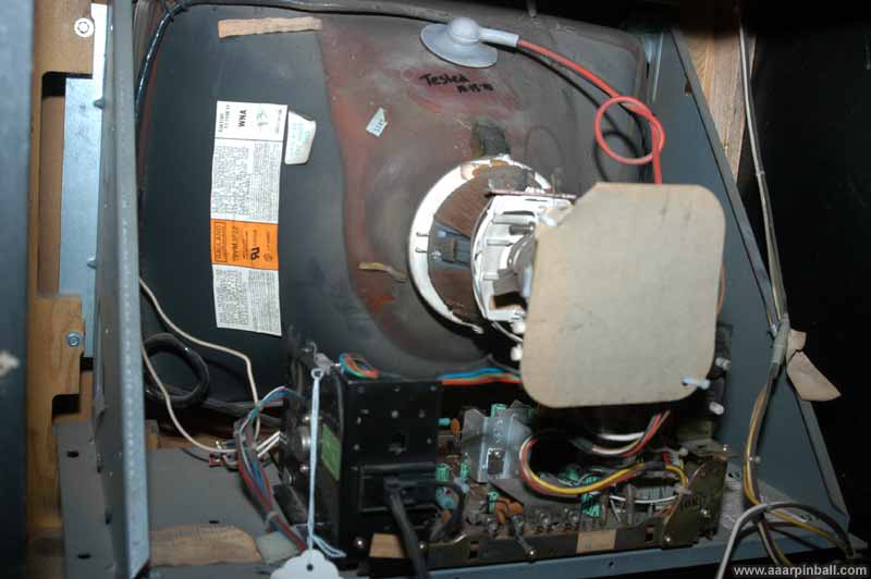
However, before even using the information from this flowchart, I could tell that fuse F901 had blown. It was unlikely that replacing the fuse would solve my problem (since they typically blow for a reason), but they do sometimes blow because of old age.
I thought replacing the fuse would be easy, but it's not. This is because Electrohome decided to use fuses that are soldered directly onto the PCB. I found that Bob Roberts sells the replacement part and ordered a few. Some people suggest replacing the fuse with a replaceable fuse (rather than soldering another directly to the PCB), but I decided to stick with the original. The parts arrived, I replaced the fuse, and the monitor still didn't work. At this point I started using the G07 flowchart.
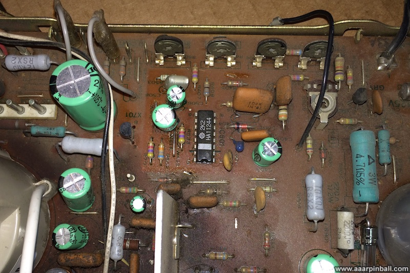
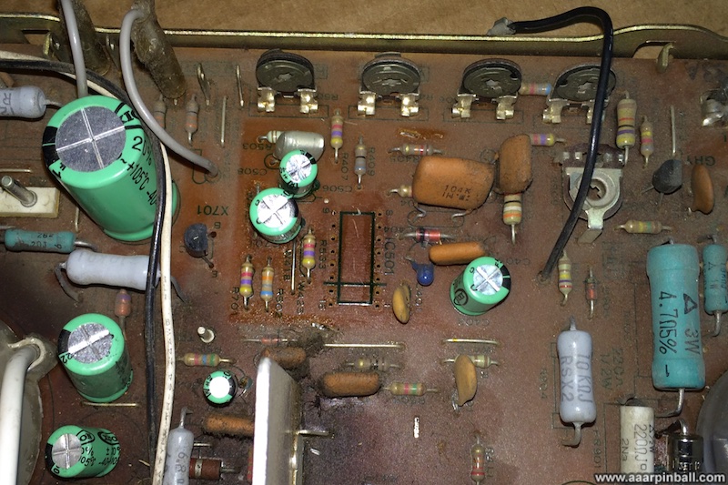
I checked the B+ voltage. It was high, measuring around 153VDC. I then removed transistor X701 to determine if the X-ray circuit was causing the problem. I found out that wasn't the cause, the B+ voltage was still high, and soldered X701 back. At this point I decided to order a replacement IC501, which is the horizontal deflection IC. This chip is obscured by a metal shield. The picture below shows the chip after the metal shield is removed.
Followed by a picture of the chip removed from the G07's board.
Rather than solder the new IC501 directly to the PCB, I decided to install a socket. I figured there was a chance that this new IC would blow up (because of some root cause I had not yet identified). I installed the socket and the new IC501. I'm not showing a picture of the socketed IC501 because it doesn't look significantly different that the picture above.
I turned on the game... let the monitor warm up for 10 or so seconds... and ... IT WORKED!
Fixing Slightly Jumpy G07 Monitor
Original 8/3/2016
After repairing my G07 monitor, I noticed the image could be a little jumpy. By jumpy I mean the image would appear to bounce just a little from time to time. After watching the game for some time, I was able to correlate the little bounce to what the game was displaying.
From time to time, Marble Madness will put black boxes with text inside layered on top of the game's video. These text boxes contain hints or other information. I noticed the screen would get slightly larger when more black was displayed. Since the game would draw these boxes and then remove them, a little bounce would occur.
Using the diagnostics screen, I was able to show this with certainty. One of the diagnostic screens displays a portion of a Marble Madness level and you are able to move it around the screen. If you move the level down, the screen ends up filling with black. As I moved the level down, I could so the static diagnostic text slightly moving upward.
Having found that a monitor's B+ voltage will impact image since when working on Tempest, I decided the B+ voltage should be checked. I hooked an alligator clip to the suggested test location (and connected another clip to the chassis frame) to measure B+. See the image below.
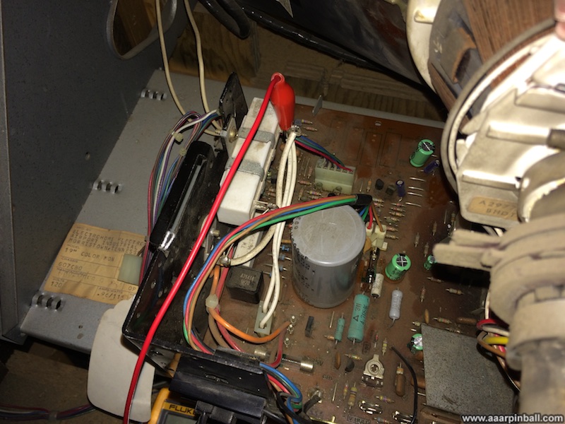
The DMM read 105VDC. That was low since the G07 manual states the B+ voltage should be 120VDC. Luckily this is an easy adjustment since there is a pot on the board that is used to fine tune the B+. With a little adjustment I got the B+ to 120VDC.
This did impact the picture size as well as the brightness. After some adjusting, the slight bounce was gone! I didn't see it while playing the game or when doing the diagnostic test I mentioned above. Also, I was pleasantly surprised to find the image looked better than ever! While it's pretty much impossible to take a picture of a monitor that shows the monitor's quality, here is an attempt below.
Track Ball Rebuild
Original 2/15/2014
I've thought about rebuilding the track balls in Atari's Marble Madness since I first purchased it. Since rebuild kits are around $25 each (one per track ball) and the track balls were paying well, I never made it priority.
A couple of weeks ago I needed to place a parts order and decided to toss in a single track ball rebuild kit. I thought I'd rebuild one of the track balls on Marble Madness and see whether the improvement warranted rebuilding the other. The rebuild kit arrived and it put it off to the side while I completed another project. A funny thing occurred during this time. I was looking for a part that I though I ordered a year or two ago and I came across another track ball rebuild kit. Apparently I had "tossed in" a rebuild kit a year or two ago and forgotten!
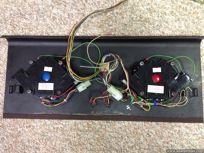
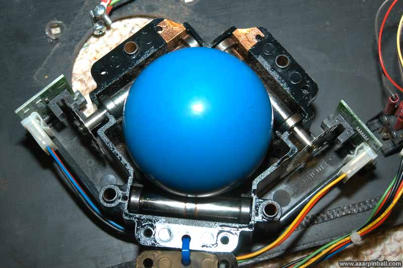
Since I had 2 rebuild kits now, I decided to rebuild both track balls. It turned out to be a very simple process that starts by removing the Marble Madness control panel from the cabinet. The image below shows the bottom of the control panel after it has been removed.
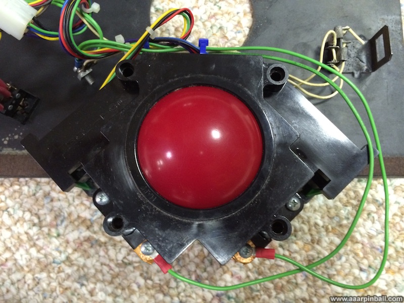
With the panel removed, the 4 bolts that hold each track ball need to be removed. Below is the trackball disconnected from the control panel.
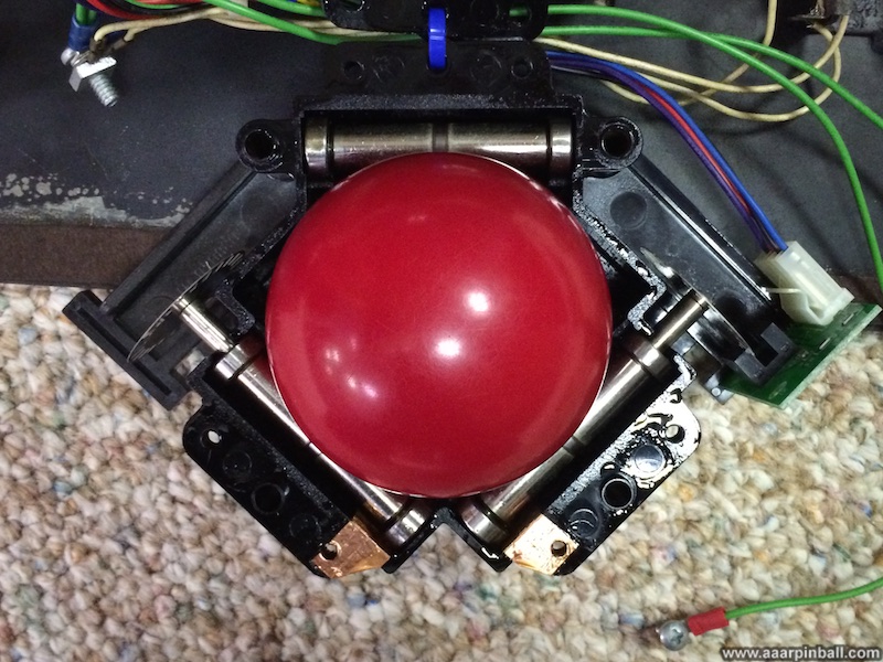
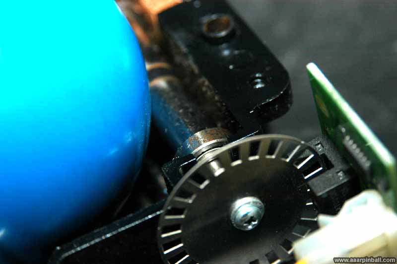
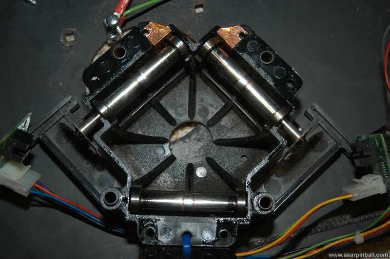
In order to access the innards of the track ball, 6 screws must be removed. Once removed, the top of the track ball mechanism can be removed to expose the ball itself as well as the 3 rollers, interrupters, and various circuit boards. This is shown below. You can also see the wear spots on the rollers from years of use.
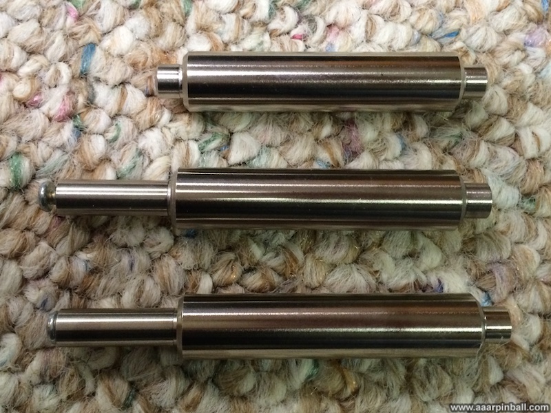
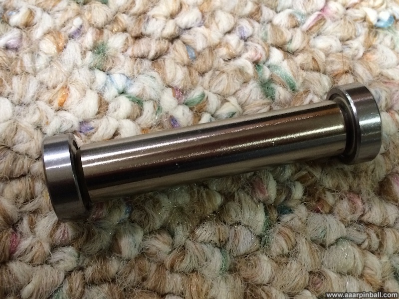
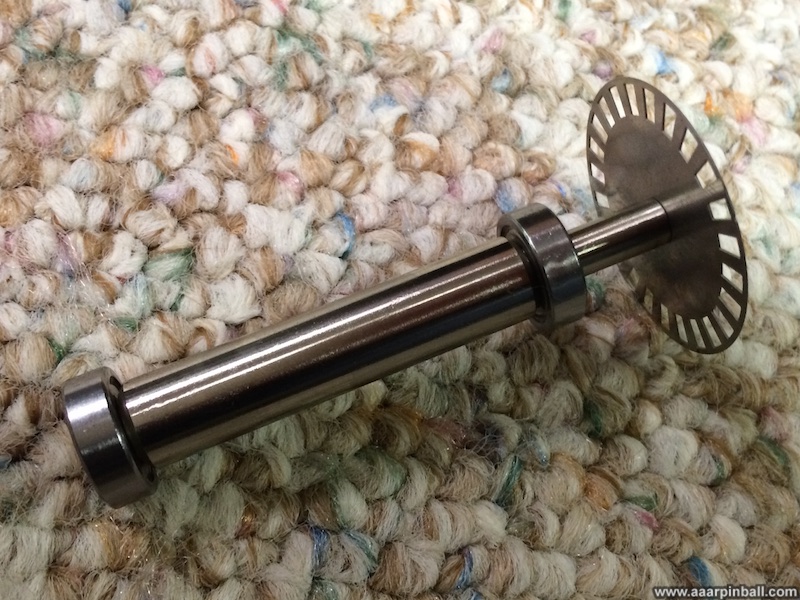
Everything just lifts out at this point. The ball comes right out as well as the 3 rollers. All 3 of the rollers have bearings on each side (for a total of 6). Two of the rollers have round discs attached to one end called an interrupter. The new rollers are shown below followed by a roller with new bearings. Finally, a new roller with bearings and interrupter is shown.
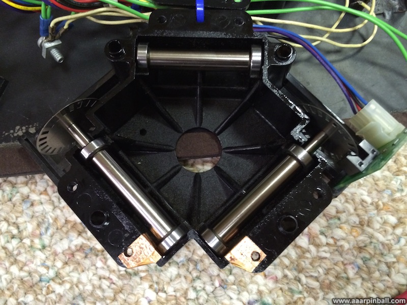
Starting the rebuild, the three rollers easily drop into the casing with a tiny click. The installed new rollers are shown below.
To finish up, the trackball is placed into the middle and all the screws and bolts are installed. Once completed the trackballs did spin more smoothly than before. However, the difference was not huge. This was not surprising, perhaps, because the original mechanism was working fairly well before the rebuild.
Control Panel Artwork Restoration
Original 1/2/2011
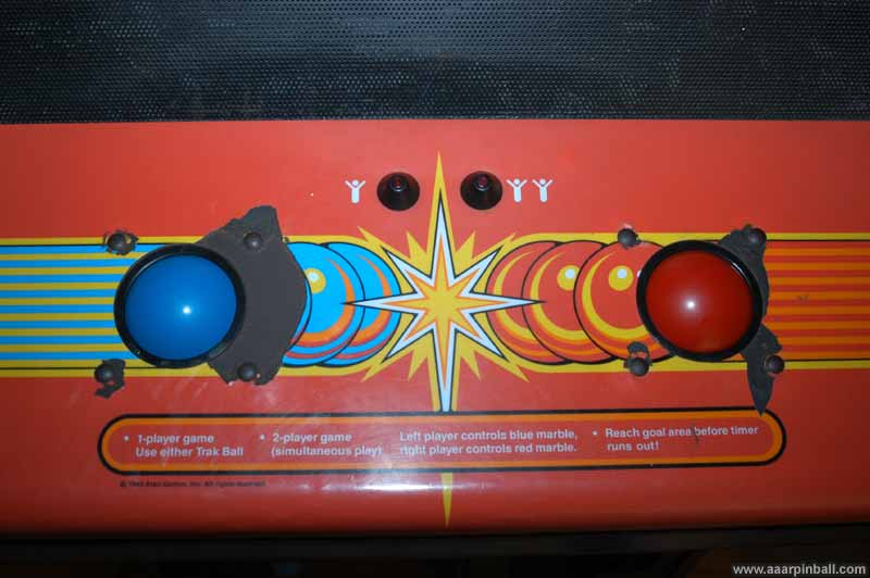
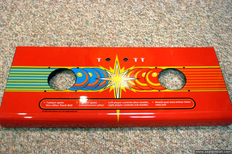
The original control panel was not in very good shape. The condition did not effect game play, but it certainly doesn't look appealing. See for yourself by looking at the picture below.
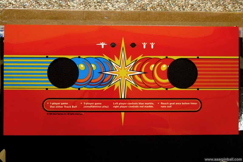
I've replaced the control panel artwork with a high quality reproduction. A picture of the Marble Madness repro control panel overlay (CPO) is shown below. Note that the weird line going across the player 1 icon is a reflection from a light in the room.
I used the "grill" method to remove the original artwork from the Marble Madness control panel. This involved heating my outdoor grill to about 500 degrees and placing the control panel in the grill for about 10 minutes. Aluminum foil was placed on the grill so that the control panel and plastic wouldn't get on the cooking area. All the electronics, wiring, etc. were obviously removed before putting the control panel into the grill!
After about 10 minutes passed, I opened the grill and used a putty knife to start peeling away the artwork. It came of pretty easy, but the grill was very hot and the heat rising from the grill could easy burn. Be careful! I ended up closing the grill and heating the control panel up again. This time I took the control panel out of the grill, allowing me to work on removing the artwork without 500 degree heat on my hand.
The original artwork was interesting to work with. Within just a few seconds of pulling it from the hot control panel, it would harden. Using protection on my hand, I was able to use the hardened artwork to pull the softer artwork off the metal.
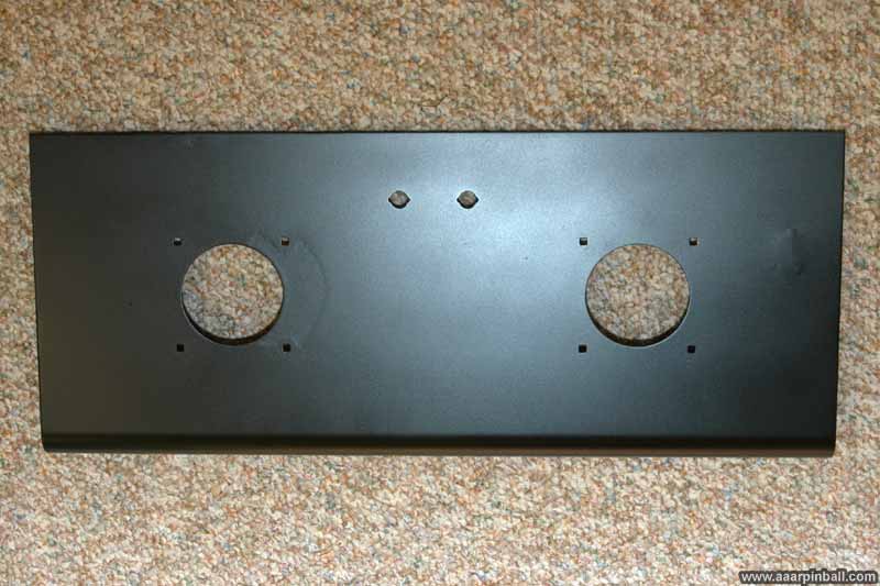
When all the art was removed and the metal cooled down, I used sand paper to remove the remaining gunk. I did a coat of primer and then a coat of satin black. The result is shown below.
If you look closely at the left track ball area, you can see some imperfections in the paint. It turned out that the metal itself was rubbed so much over the years that it wore inconsistently. If you look at the original control panel picture above, you will see this area matches the area where the original art had worn off. I tried sanding this area, but it didn't have any significant effect. While there is clearly a texture in the picture, it was actually very smooth.
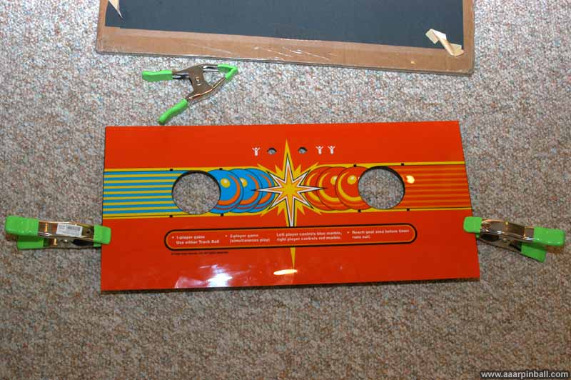
The image below shows the prep work to install the Marble Madness CPO decal. I used clamps to hold the decal in place after it was lined up.
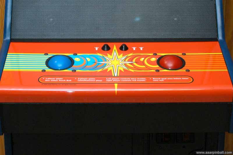
And... Ta-dah! The final product is shown below. Turned out excellent! I'm very pleased with the result. This is the first CPO I have installed.
And below is a picture of the populated control panel.
Cabinet Restoration (Removing Side Art)
Original 11/14/2010
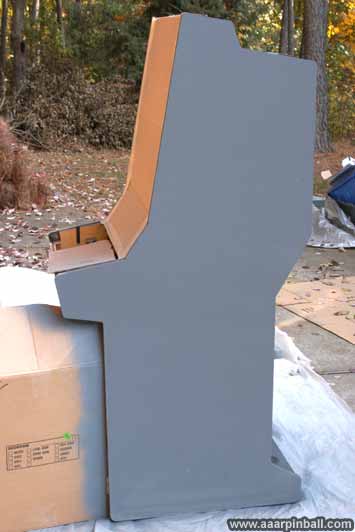
My Marble Madness cabinet wasn't in bad shape at all. It certainly wasn't in great shape, it had a well used but not destroyed look. I decided I'd make Marble Madness my first cabinet restoration. Even with all the pin work I've done, up to this point I had never replaced side art.
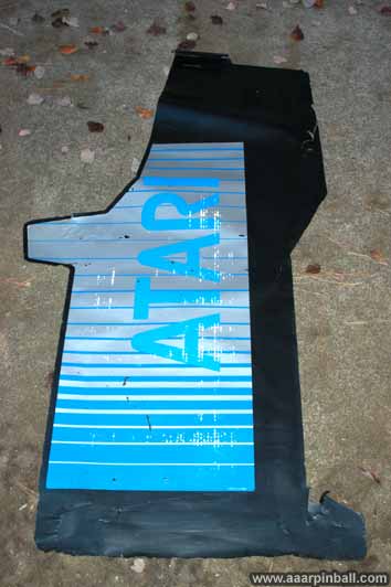
I was surprised to find I could peel off the "Atari" side art. I'm referring to the graphic art, not the black material behind it. However, since the black material itself was peeling off in some places, I decided it would be silly to attach new (expensive) side art onto it. I ended up removing the black material and therefore also removing the Atari side art.
I keep using the term "black material" because there is some debate as to what material it is. Some say it is vinyl. Others say it is melamine. I really don't know, but I'm happy to say I was able to peel it off rather easily. It took about 30 minutes to remove the material from both sides.
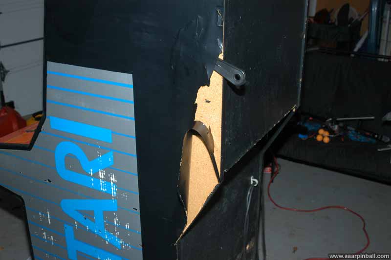
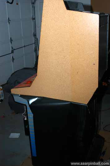
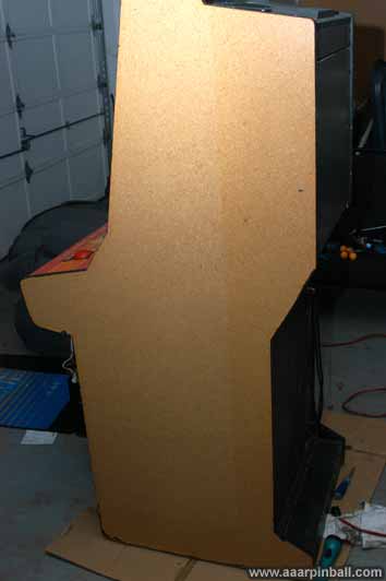
The image below shows that the side came off in a single piece!
In addition to removing the black material from the sides, I removed it from the wood surrounding the coin door.
Cabinet Restoration (Bondo)
Original 11/14/2010
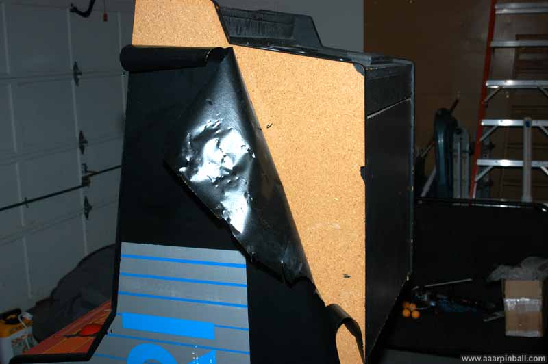
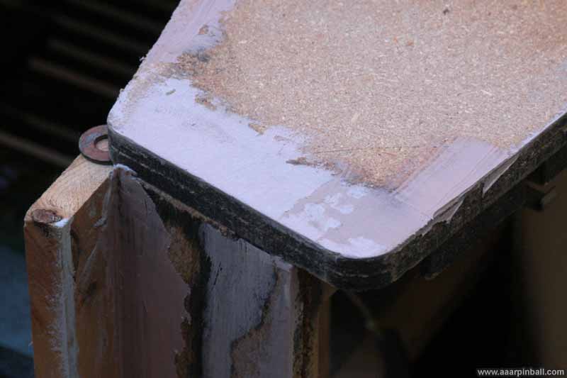
I used Bondo to patch up some areas of the cabinet. The bottom of both sides was pretty beat up. Also, the areas around the control panel needed some improvements. The picture below shows how I used a 2x4 to ensure the bondo repair was straight.
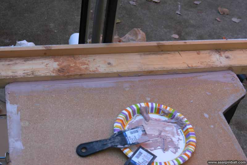
I had to manually work on the cabinet by the control panel. I didn't find any object around my house that had rounded corners. The picture below is of the work in progress, but it turned out pretty nice. You can also see another board that I used to ensure the bondo work maintained a straight edge when repairing the wood on the front of the control panel.
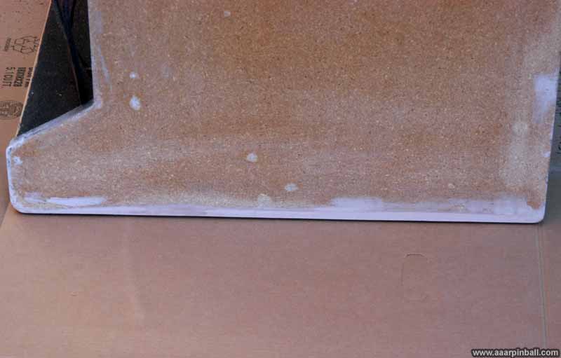
Below is a picture of the restored cabinet side bottom.
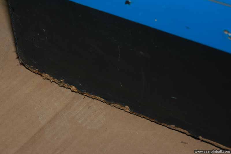
Below is a picture of the cabinet bottom before it was repaired (so you can compare).
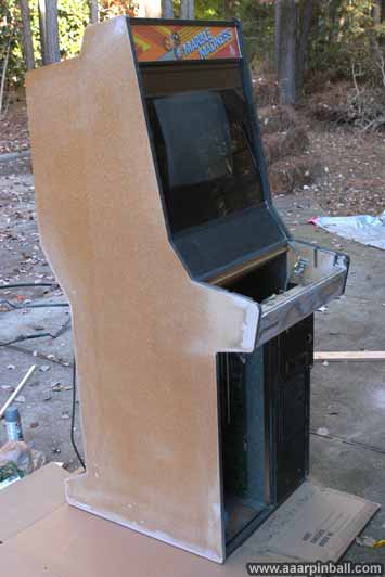
Below is the cabinet after the bondo stage was complete.
Cabinet Restoration (Painting)
Original 11/14/2010
Paint or Vinyl, that is the question. Some purists want vinyl (even though there is debate whether the cabinet actually had vinyl --- as mentioned earlier, some say it was melamine). I went with paint for a couple of reasons:
-
I'm familiar with paint, it seemed easier
-
It's easy to purchase paint locally
-
The decals will cover up 2/3s of the cabinet
-
I knew that painting could create a very nice looking cabinet
I started by sanding the cabinet sides with 60 grit. I then put down 2 coats of primer, sanding with 220 after each coat. This was followed by 4 coats of Satin Black. After the first two, I sanded with 220 grin. For the last two, I sanded with 1000 grit. Below is a picture of the cabinet with the primer, followed by a picture of the final product. Looks nice!
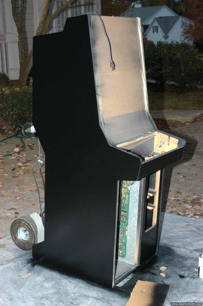
(I was asked if I painted with the PCBs exposed. No, I didn't. While I was painting there was a cardboard mask covering the PCB area.)
Cabinet Restoration (Side Art)
Original 12/14/2010
This was my first attempt to install large decals. I was a little nervous, but did a lot of research and felt like I knew what to expect. I settled on the "dry" method, which is the approach where you apply the decal directly onto the surface knowing that once it sticks it is there forever. No second chances with this approach. There is an alternative "wet" method which is more forgiving. While many people swear by it, I didn't like the idea of applying any amount of liquid to my cabinet.
I started with the right side of the cabinet (from the perspective of playing the game). I positioned the art very well but ended up with a couple of air bubbles. Nothing terrible, but I was annoyed when I noticed them. One tip: look at the art from different angles while doing the install. I couldn't see the bubbles from my angle during install!! I grade my right side result with a "B". It's pretty good. I don't think average Joe would even notice the imperfections.
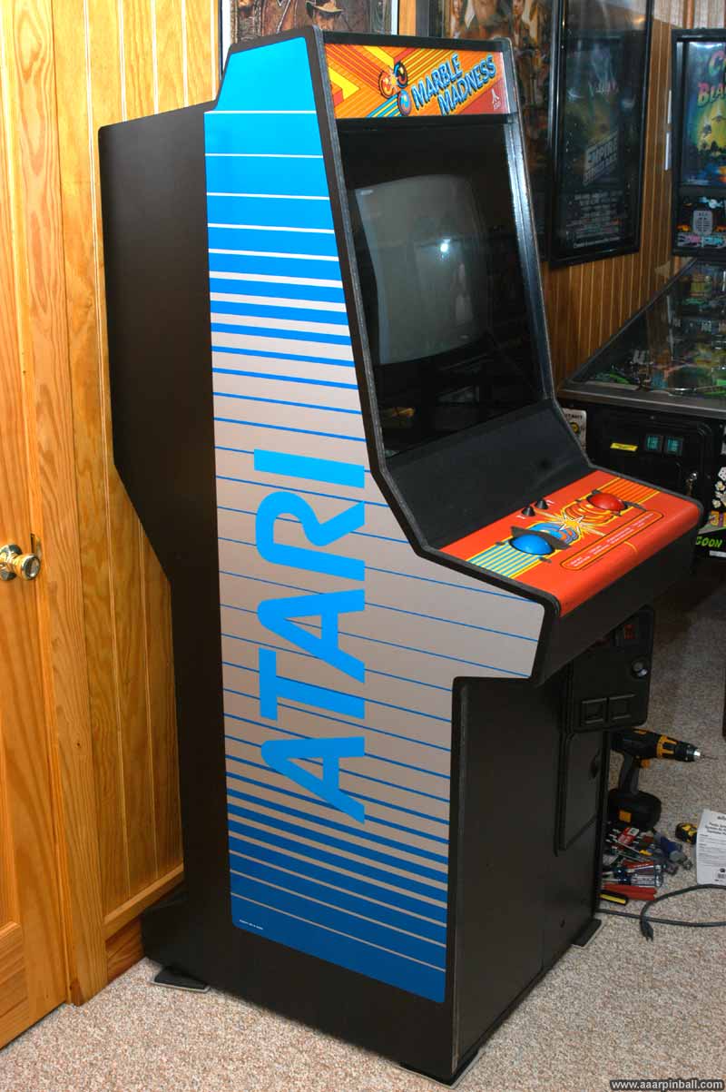
I moved on to the left side. I took more care to look for bubbles and went a little slower. It turned out excellent! Very good positioning and no bubbles! I grade the left side as an "A". You can see the results below.
As you can see, in this picture the control panel still needs to be redone. Also, the T-molding needs to be installed.
Below is the grade "B" right side. Looks good in the picture, but there are some bubbles...
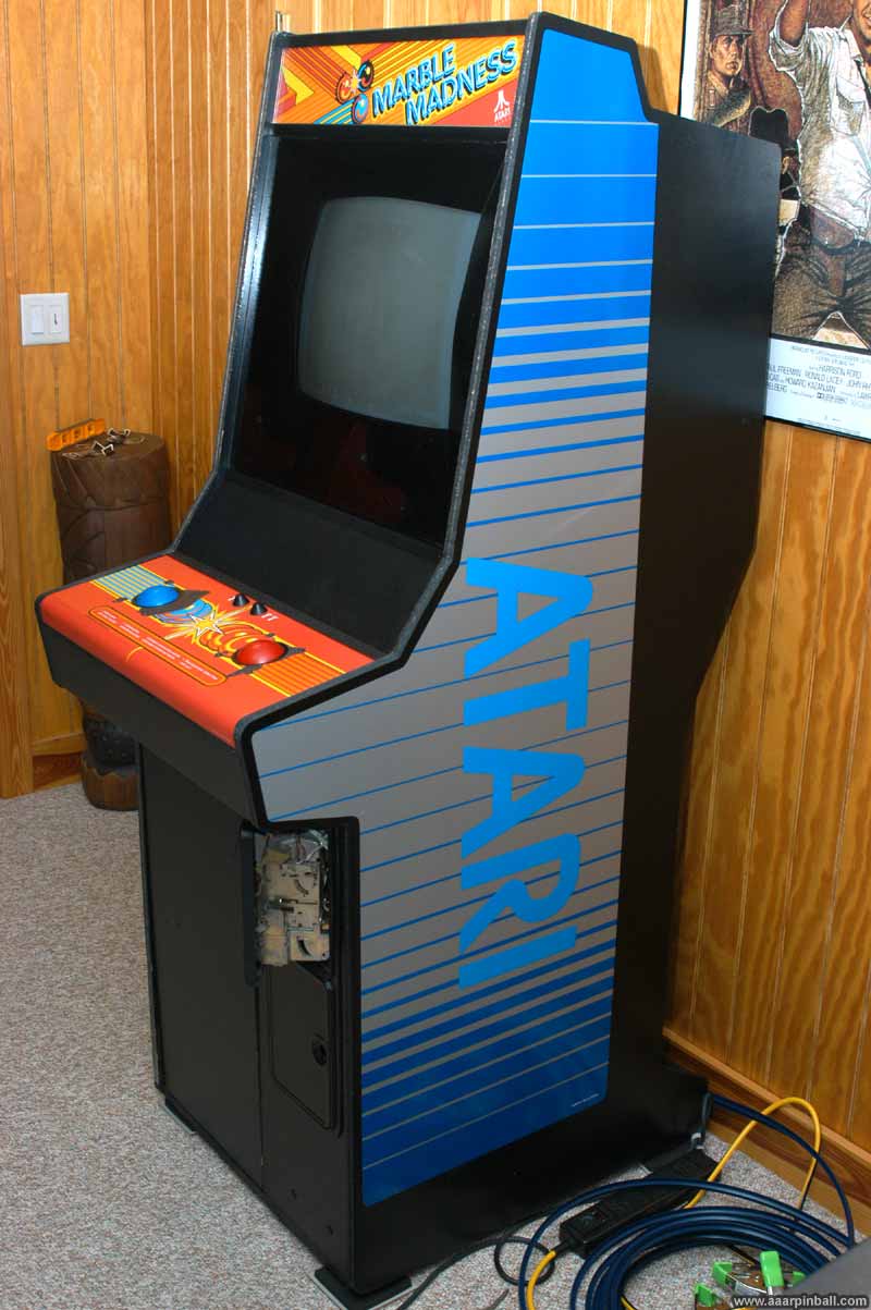
Restoration Complete!
Original 1/4/2011
Here she is...
As you can see, I went with the dark blue t-molding.
Volcano Switches
Original 1/1/2011
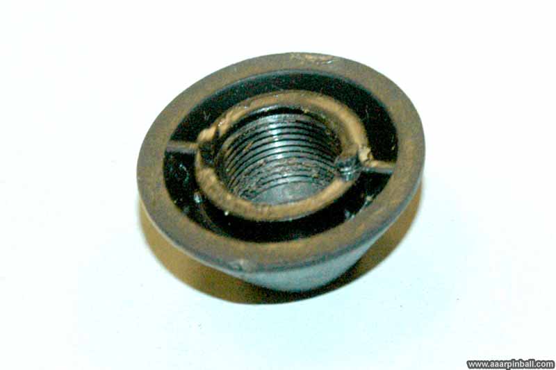
The classic Atari volcano player 1 / player 2 buttons needed to be removed in order to replace the Marble Madness control panel. I found out that the cones have little protrusions that fit into slots on the control panel. This keeps the cone from turning and ultimately dislodging itself from the control panel. The two slots in the control panel for the volcano switches are shown below. By the way, this picture was taken after I primed the control panel, which is why it is gray.
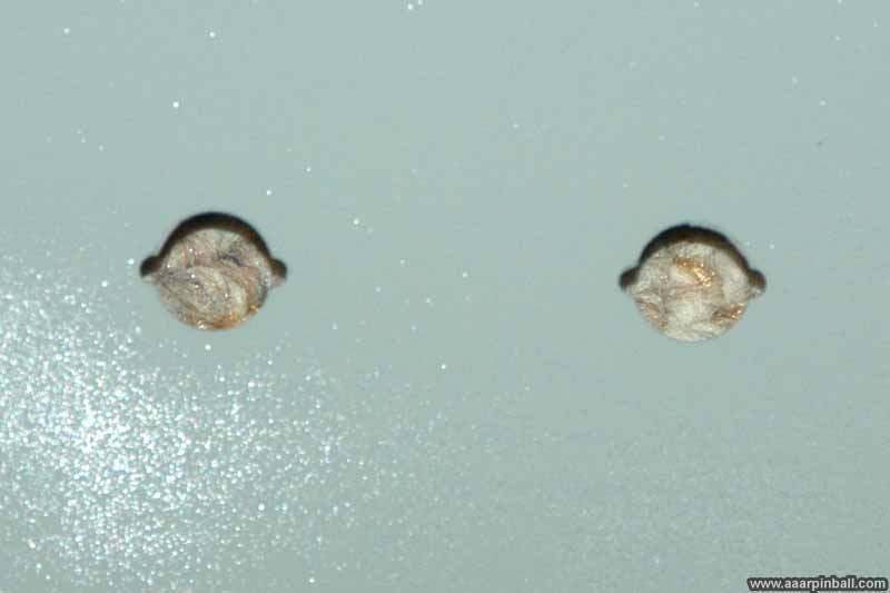
Below is an over exposed picture of the bottom of a cone switch. The two protrusions are a little blurry but can be seen just on the outside of the threaded area.
Atari Volcano Switch Repair
Original 1/9/2011
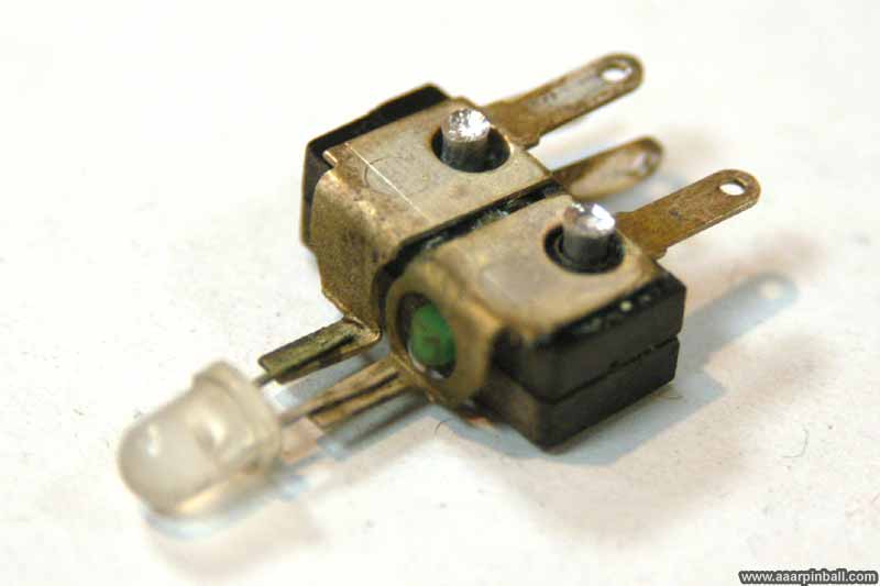
The Player 1 switch wouldn't register. After closer inspection, I found that one of the leads from the switch had broken off. There should be 5 connectors, the picture below shows my switch only had 4. The missing one should be at the very right of the switch below. You can see a broken connector that is pretty flush with the surface.
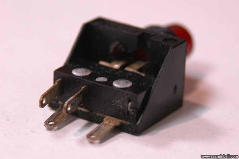
The Atari volcano switch is composed of a few separate parts that are riveted together. There is the outer housing, the LED with its connectors, and the actual switch mechanism. I used a drill to drill off the rivets. While I did fine on the leftmost rivet, I went just a little too far on the rightmost rivet and a small part of the outer housing broke off. No big deal, but still disappointing.
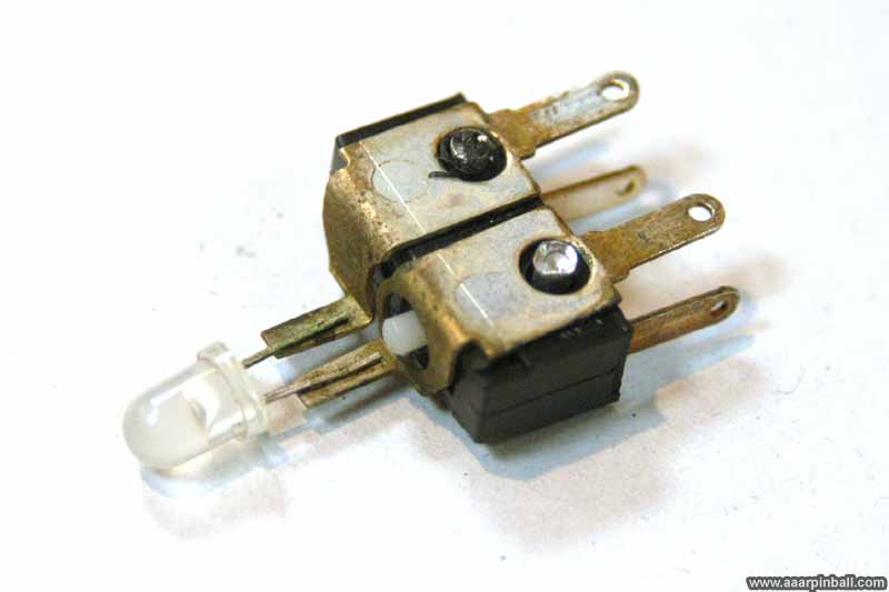
With the rivets removed, I removed the outer housing. Below you can see how the diode part simply lays between the outer housing and the inner switch.
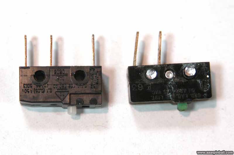
From my pinball parts, I had a switch that was very similar. Rather than try and open up the broken switch and figure out some way to reattach the broken connector, I decided to try this very similar part. You can see how similar the two parts are below. The new part is on the left and the original part is on the right.
Below shows the diode part added to the new switch.
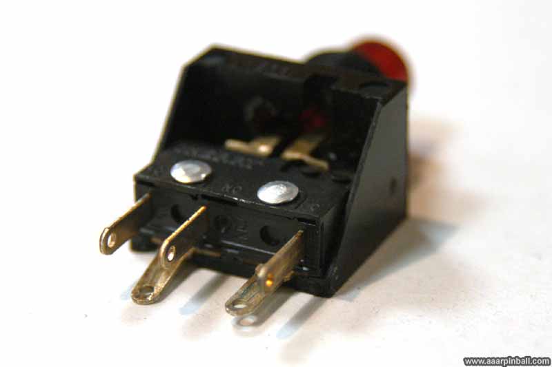
This picture below shows the outer housing added to the new switch with the diode part. I don't have any rivets, so ended up using hot glue. I normally don't like using hot glue for anything, but it is working in this case. It is very sturdy, but definitely a hack.
Coin Door
Original 1/22/2011
To restore the coin door, I used the "hammered and satin" approach. After removing the coin door and cleaning, I used hammered black spray paint follow by black satin. The hammered does an excellent job of providing the texture, but the color doesn't look quite right. Putting a coat of satin black on after the hammered provides a very good color and keeps the hammered texture. See the result below.
Coin Door Lights
Original 1/22/2011
The coin door lights were not working. I ensured the bulbs were good, but that didn't help.
I then used my volt meter and did not measure any voltage. After some investigation (reading
the schematics) I found that the power supply has a 6.3 VAC output (among other outputs). It
uses fuse F6. Since 6.3 VAC is what the schematic says should go to the coin door lights, I
checked fuse F6.
Not too surprising... It was bad.
It is a 250v 4A slow blow. I did not have any of those, but I did have a "lesser" fuse rated
at 250v 3A, which is safe but might blow too often. I installed it, turned game on, coin
door light working.
Strange Pair of Wires Hanging Down
Original 11/7/2010
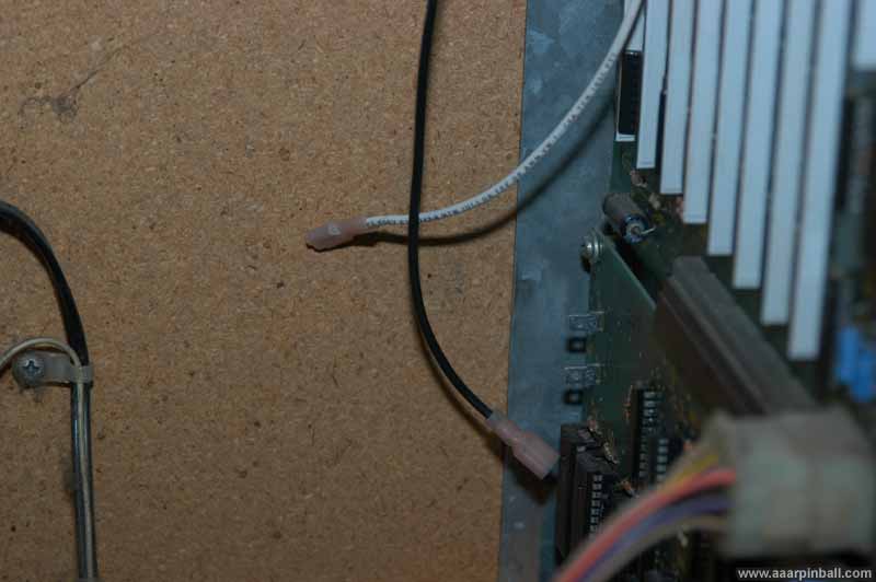
While familiarizing myself with this machine, I noticed two wires hanging down by the Marble Madness daughter card. The game way playing just fine without them connected, so I didn't connect them to anything. However, as the picture below shows, it looks like they could be connected to those two lugs.
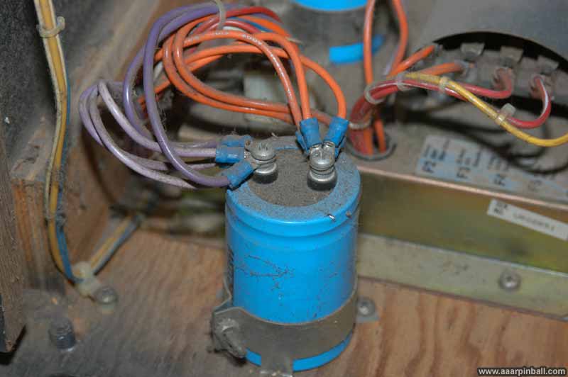
I traced the wires up toward the monitor and discovered the come from a splice in the monitor's power supply. This is shown in the picture below.
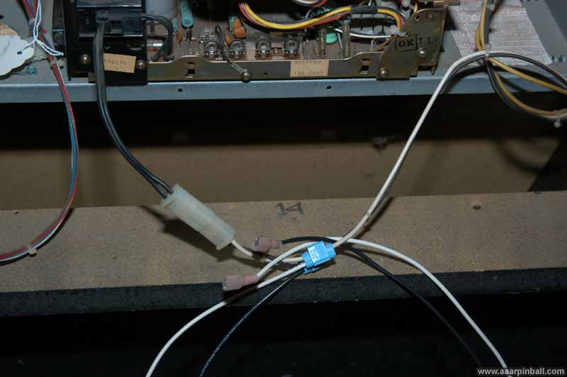
I don't know if this was a modification made by an operator or what the wires were used for, but I'm tying them up and leaving them alone. If anyone knows the purpose of these wires, please drop me a note.
System 1 Power Switch?
Original 11/7/2010
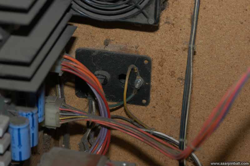
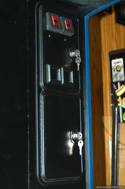
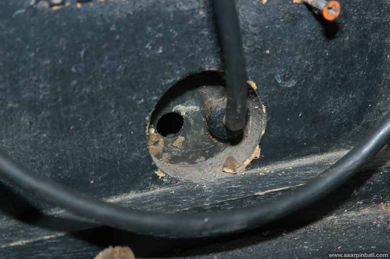
I was unable to locate a power switch for my Marble Madness when I first wanted to turn it on. I found that when it was plugged into the wall, it turned on. After some research, I learned that System 1 games should have a switch and this switch should be located right next to the power cord. Well, not in my case. There is a hole for the switch, but no switch. Oh, it's also worth mentioning that the hole was filled with gross old bubble gum. Who in the world would have gotten behind the machine and stuffed gum in there?
I did find the switch. It was inside the cabinet.
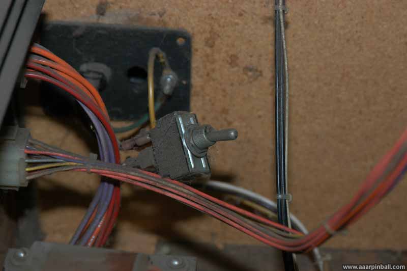
I'll clean it up and reconnect it such that it is accessible on the outside.
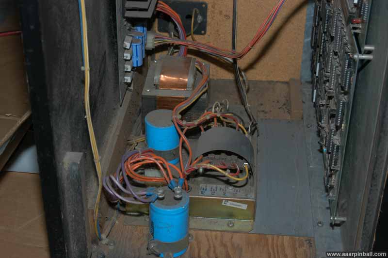
Dust Anyone?
Original 11/8/2010
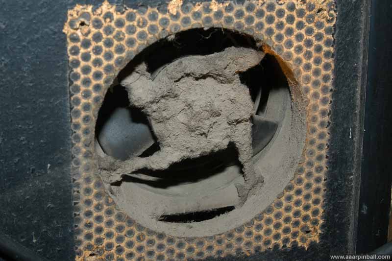
Below is a picture of the fan after I remove the protective grate. Yuck. That's anywhere from 1/4" to 1/2" of dust!
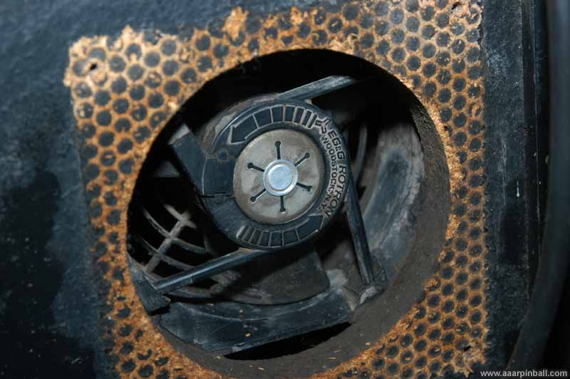
I did a quick cleaning and it looks much better! See below. Way to go EG&G Rotron fan... you survived a lone time and are still going. But you are a bit noisy.
Images of Track Ball
Original 11/9/2010
Miscellaneous Attract Screens
Original 11/10/2010
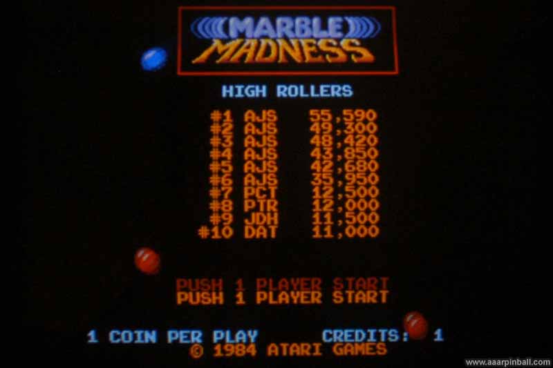
"Marble Madness HIGH ROLLERS" (above)
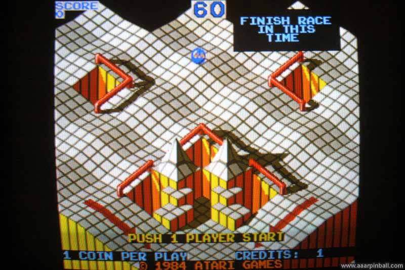
"FINISH RACE IN THIS TIME" (above)
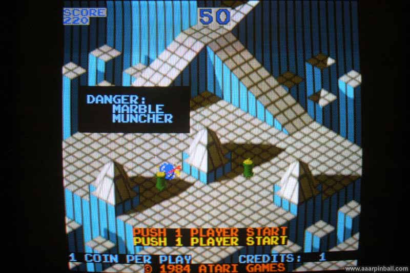
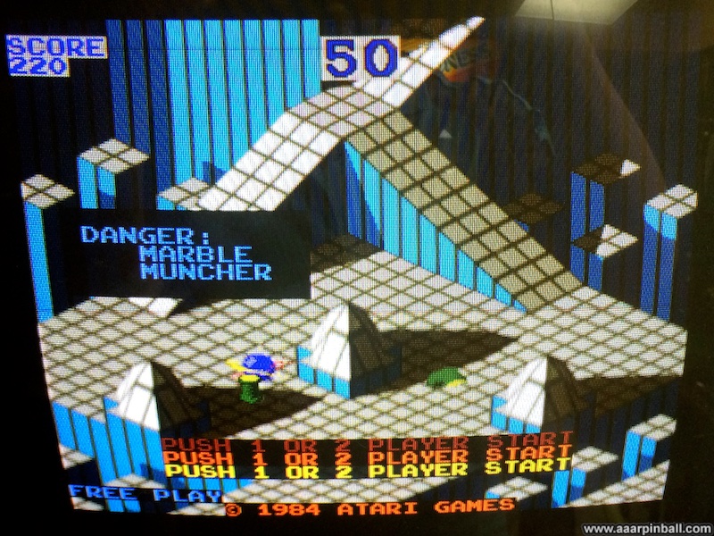
"DANGER: MARBLE MUNCHER" (above)
Spare System 1 Main PCB
Original 8/23/2011
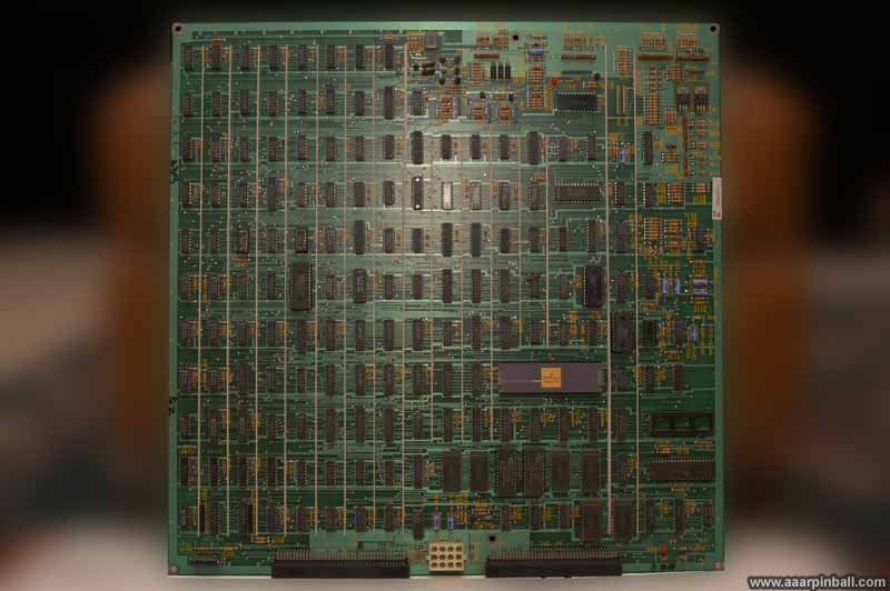
Before I purchased my Marble Madness, I found an Atari System 1 PCB for sale. This is the main PCB used in all System 1 games. Atari designed the System 1 to support multiple games using the same hardware. To accomplish this, a game "cartridge" must always be connected to the System 1 main board. The "cartridge" is really just another PCB. In addition to Marble Madness, other System 1 games include Road Blasters, Indiana Jones, Road Runner and Peter Packrat.
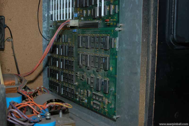
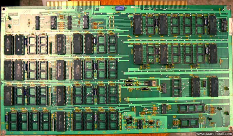
The three pictures below show a System 1 main PCB. This is the "TTL" type (revision C). A later version of the System 1 board used fewer chips and was referred to as the "LSI" version.
A picture of the Marble Madness cartridge is shown below.
The Atari System 1 PCB for sale was listed as "untested", which typically means you should assume it doesn't work. Because I wanted to have some spare parts for when I eventually got my Marble Madness, I went ahead and purchased it. When I finally found a Marble Madness, I ignored this untested System 1 PCB and focused on restoration of the full game. The untested PCB was ignored for 9 months or so.
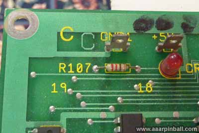
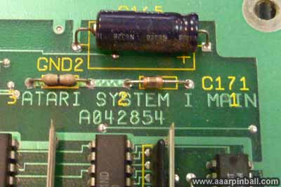
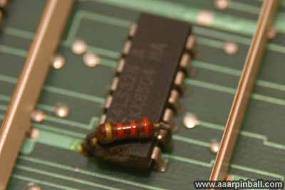
In mid August 2011 I decided to check out this System 1 PCB. I examined it closely, looking for anything that was obviously wrong. Two items struck me initially. One chip had a resistor soldered between two pins and a second chip had wires connected to it. Looking closer at this IC, on the back I could see the traces to the chip had been cut. I suspected someone accidentally did this and then repaired the problem using wires.
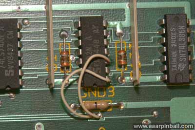
After looking at the untested System 1 board, I started the process to install it (and test it!). I removed the support screws from my Marble Madness cartridge and pulled it from the (working/tested) System 1 PCB. I then removed the cables from the working System 1 PCB, as well as the screws holding it in place, and took it out. I was quite surprised to see my working System 1 PCB had the same wires and additional resistor. It even had the same cut across the traces. These appear to be "fixes" to the PCB design performed during manufacturing, not some repair performed during the boards lifetime.
I didn't want to plug my working Marble Madness cartridge into the untested System 1 PCB right away. I wanted to at least do a little "smoke test". I installed the untested System 1 PCB and connected the power and video cables. I was happy to see "no cartridge" flash on the screen. That seemed like a pretty good start. Displaying text requires a lot of functionality to be working.
I connected the Marble Madness cartridge and powered it up. To my surprise, it booted and started displaying the attract mode. The graphics looked great! I was further surprised to see it was running in free play mode and had non-default high scores. The non-volatile RAM appeared good also. It would appear that my untested System 1 PCB was last used in a Marble Madness.
But then it happened... The attract mode music started. Yiikes! It was loud and distorted. I thought that I had accidentally hit the AR-III volume knob while swapping the PCBs, so I turned the volume down. That solved the loudness but the sound was still distorted.
I swapped everything back to the known working combination and found that everything was fine. The volume needed to be turned back up, indicating I had not accidentally adjusted it.
Bottom line: my "untested" Atari System 1 PCB had audio issues. Other than audio, however, everything seemed good. I started digging into how the Atari System 1 PCB handles audio.
Atari System 1 Audio Problem
Original 8/23/2011
Working to understand what might have caused my spare System 1 PCB to have loud and distorted audio, I began looking at the System 1 schematics. Atari's SP-277 document ("Schematic Package Supplement to Atari System I Operators Manual") contains a ton of good info. Because both of the System 1 PCBs I have are the TTL type, this document is appropriate. Atari later made an LSI version of the System 1 PCB. There is a separate Atari document for that version.
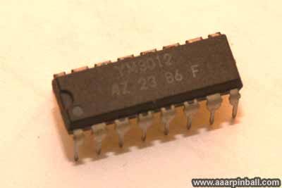
The diagram below is my summary of how Atari System 1 audio works.

The System 1 design supports two sources for audio: (1) a Yamaha 2151 and (2) an Atari Pokey. The 6502 processor runs the audio show by telling either the Yamaha 2151 or the Atari Pokey what to do. IMHO, anything you hear from Marble Madness that sounds pretty cool (such as all the background music) comes from the 2151. The Pokey seems to be used for short duration sounds effects. While the Pokey includes its own D/A converter, the YM2151 requires an external D/A. The YM3012 is used for this purpose. Both the 2151/3012 output and the Pokey output are amplified individually using the LM324 op-amp. After an initial amplifications stage, the two sources are combined and amplified again. This mixed audio is then provided to the AR-III board to output to the speakers. The YM2151 supports stereo audio (left and right channels). The Pokey support a single audio channel (mono) which is mixed into both the left and right channels.
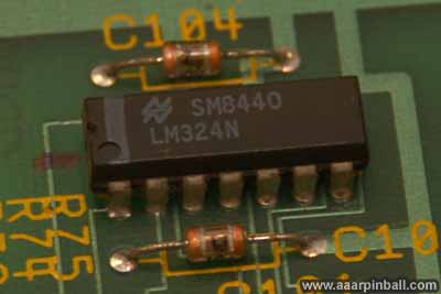
Because the audio was distorted and loud, I initially thought there might be a problem with the op amps. The amplification is performed by LM324 chips. There are 3 of these LM324s and I replaced all 3. When I tested, I found the audio problem had not changed. So much for blaming the LM324s.
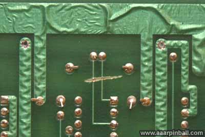
The LM324s take an input single and amplification it relative to a voltage provided to the chip. Since there was too much amplification, I thought that the voltage might be wrong and causing excessive amplification. All the LM324's are provided a -15V and +15V signal. I verified these voltages were correct. The LM324 is shown below.
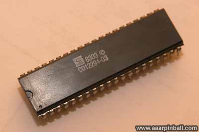
While I had not checked everything in the amp section (such as the caps), I decided to move elsewhere. Upstream from the amp section is either the 2151/3012 sound generator or the Pokey sound generator. I decided to check out the Pokey. The sound diagnostics had given me some reason to select the Pokey over the YM2151/YM312. A Pokey is shown below.
There are 3 phases to the sound diagnostics
-
Music Test. This is generated by the YM2151/YM3012. It plays a scale of sorts.
-
Effect Chip Test. This is generated by the Pokey. It plays 4 notes and then a cord.
-
User choice. This isn't the official term, but it's descriptive. The user is allow to select different sound samples. Many of these come from the YM2151/YM3012. Perhaps all, but I'm not sure
The phase 1 "music test" did not seem distorted to me. Because this is generated by the YM2151/TM3012, I thought I'd do well to investigate the Pokey. Truth be told, prior to digging into this System 1 audio issue, I never noticed exactly what the audio test was doing. I specifically never noticed there was the "2nd phase" that tests the effects chip (Pokey). If you are not watching closely, it's possible to miss it.
The Pokey is in a socket, so I pulled it out. No desoldering was needed. I booted the game without the Pokey and found it behaved exactly the same! That was a bit of a surprise. At first I thought that Marble Madness may not use the Pokey at all. That seemed unlikely, however, so I pulled the Pokey from my known good System 1 board and installed it in this board.
Now I did notice a difference. Prior to replacing the Pokey, I didn't hear anything during the effect chip test. With the replacement Pokey, audio was played during this phase of the test. The Pokey from the untested System 1 PCB was bad! However, even with a working Pokey installed, the music selected from the 3rd phase "user choice" was distorted. It was clear that my System 1 PCB had at least 2 problems: a bad pokey and at least something else.
Side note: The LM324s work by amplifying a delta in voltage. In order to determine a delta, two inputs are required. The System 1 PCB ties one input to +5V, the other input, in this situation, comes from the Pokey. If the Pokey is not installed, the input to the LM324 is floating. This means it's not a well defined value --- but it's still something. I found that grounding the output pin of the Pokey caused the audio volume to be lower than if I let the input float. Since I had a bad Pokey, was the output floating? Is that why the volume was louder than expected? I never went back to check the Pokey's output voltage when the bad Pokey was installed, but I'm guessing this was the cause of the excessive volume.
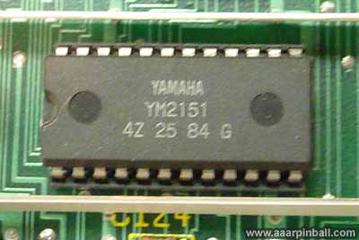
Having addressed the problem on the Pokey side of the audio, I needed to start looking at the YM2151/YM3012 side. Both the YM2151 and the YM3012 are shown below.
While it always seemed that both the left and right audio was distorted, I decided to specifically check. There is a capacitor inline with each of the YM3012 audio outputs. Capacitor C110 is for the left audio while C111 is for the right audio. I cut one of the leads on C110. This caused the left audio to go away. I could "clearly" hear that the right audio was distorted. I then temporarily reattached C110 and cut C111. Now the right audio went away and I could "clearly" hear the left audio was distorted. This further showed that there was no reason to look downstream at the amplification circuitry. So what is upstream from these two caps? The problem must be up there somewhere! The first thing upstream is the YM3012 D/A.
The YM3012 D/A is in a socket. I pulled the YM3012 from my working board and installed it in the "untested" board. The audio was perfect! This shows that the original YM3012 had not completely died, but was not performing its analog-to-digital conversion very well at all. I do find it interesting that even with the bad YM3012, I didn't notice anything wrong with the phase 1 "music test". I can only guess that the particular YM3012 failure effected the chip's ability to do more complex D-to-A conversions and playing "whole notes" didn't trigger the issue.
Bottom line:
-
The Pokey chip was bad
-
The YM3012 chip was bad
I've played several games of Marble Madness on this repaired Atari System 1 Main board and I'm happy to report it's working perfectly. Now I have a fully working backup Atari System 1 Main PCB.
Player 1 and Player 2 wiring
Original 11/7/2010
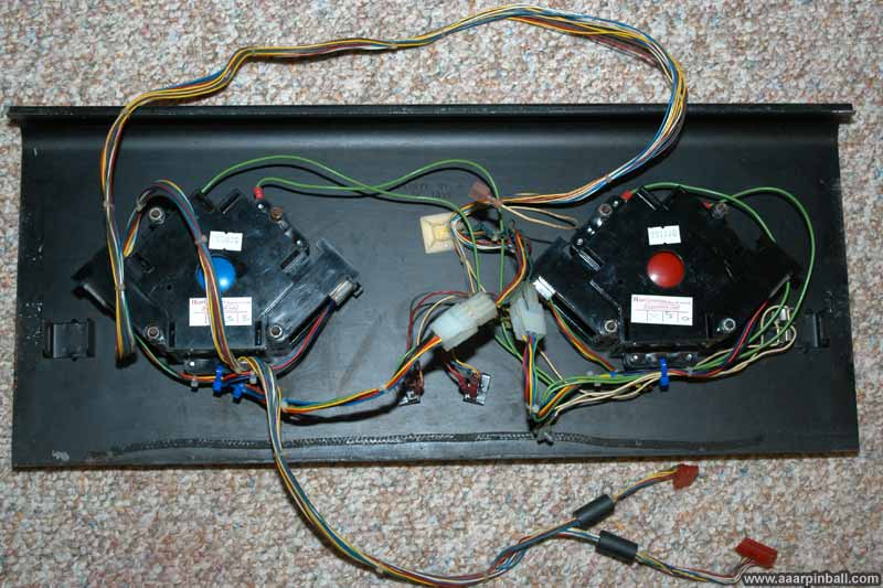
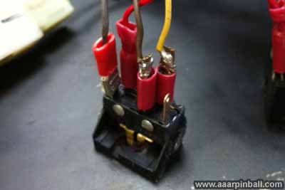
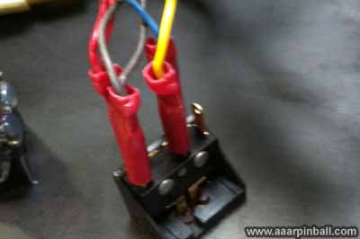
Wiring for Player 1 and Player 2 switches are shown below (in that order)
Miscellaneous Pictures
Original 11/7/2010