Williams Road Show Pinball
Repairs, Restorations, Tweaks and Insights
![]()
Introduction
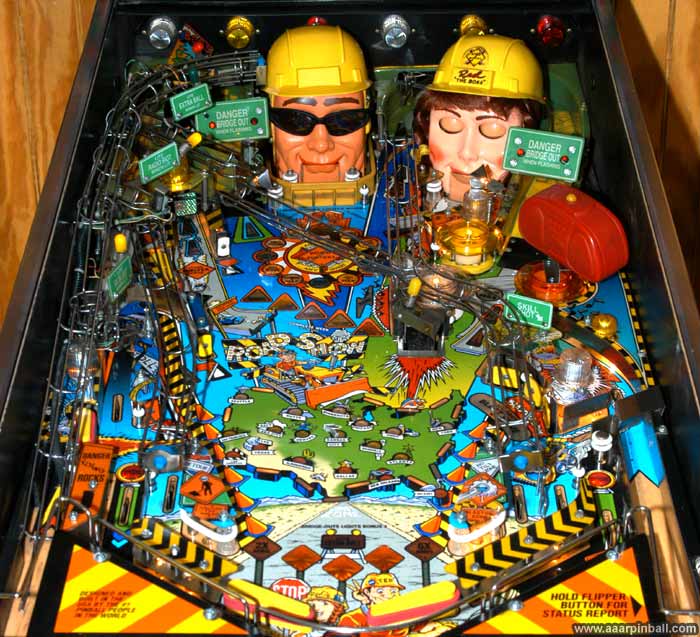
I first got introduced to Road Show at a restaurant called The Garrett in Campbell, CA. I believe this was around 1999. With two talking heads (Red & Ted), four flippers, cool wireform ramps, "flying rocks", lots of modes, and a shaker motor, this is one fun game to play.
Installing ColorDMD LCD For Road Show
May 1, 2022
I thought some people might be interested in the steps required to install a ColorDMD LCD on a Road Show pinball machine. It's really pretty simple. I think the included documentation is a bit confusing.
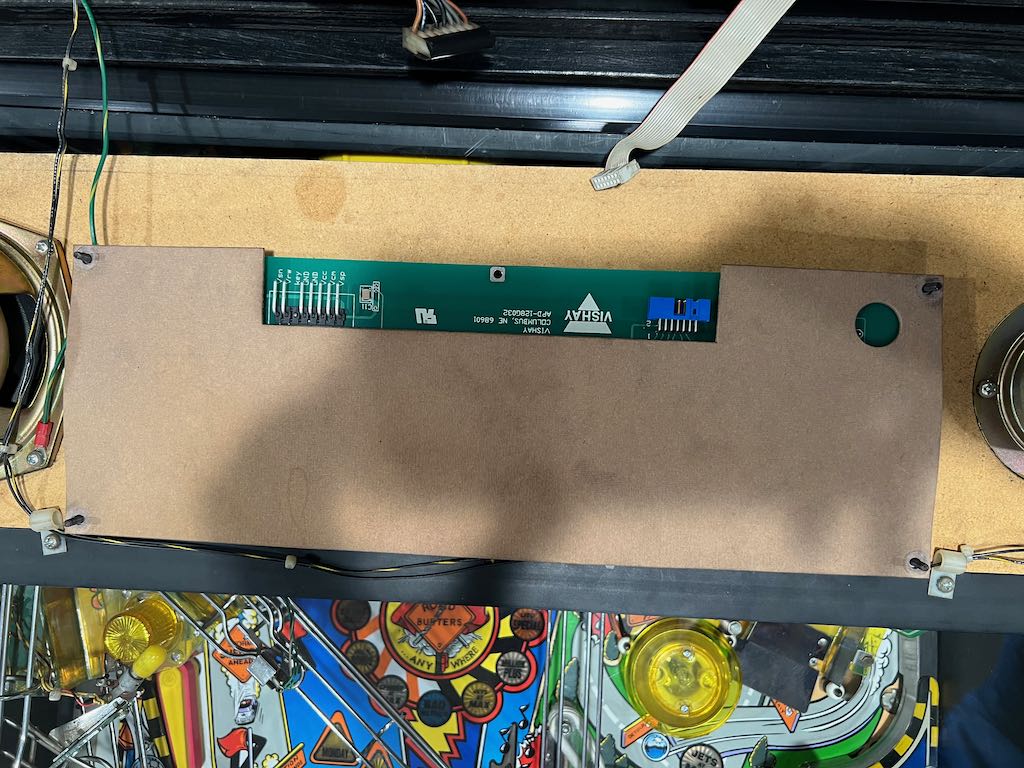
The picture below shows the original DMD. The connector on the left is the high voltage power connector and the connector on the right is the DMD signal connector.
With your pinball machine turned off, disconnect both power and signal connectors. When the power connector is disconnected, consider electrical tape for the connector end. It will not be used anymore.
Now that the connectors are removed, the cardboard protector needs to be removed. It is held in place by 4 pairs of a nuts and a washer. A nut/washer pair is on each concern of the DMD. Note: mine was missing a nut/washer in the lower left. The picture below shows the 4 nut/washer pairs removed.
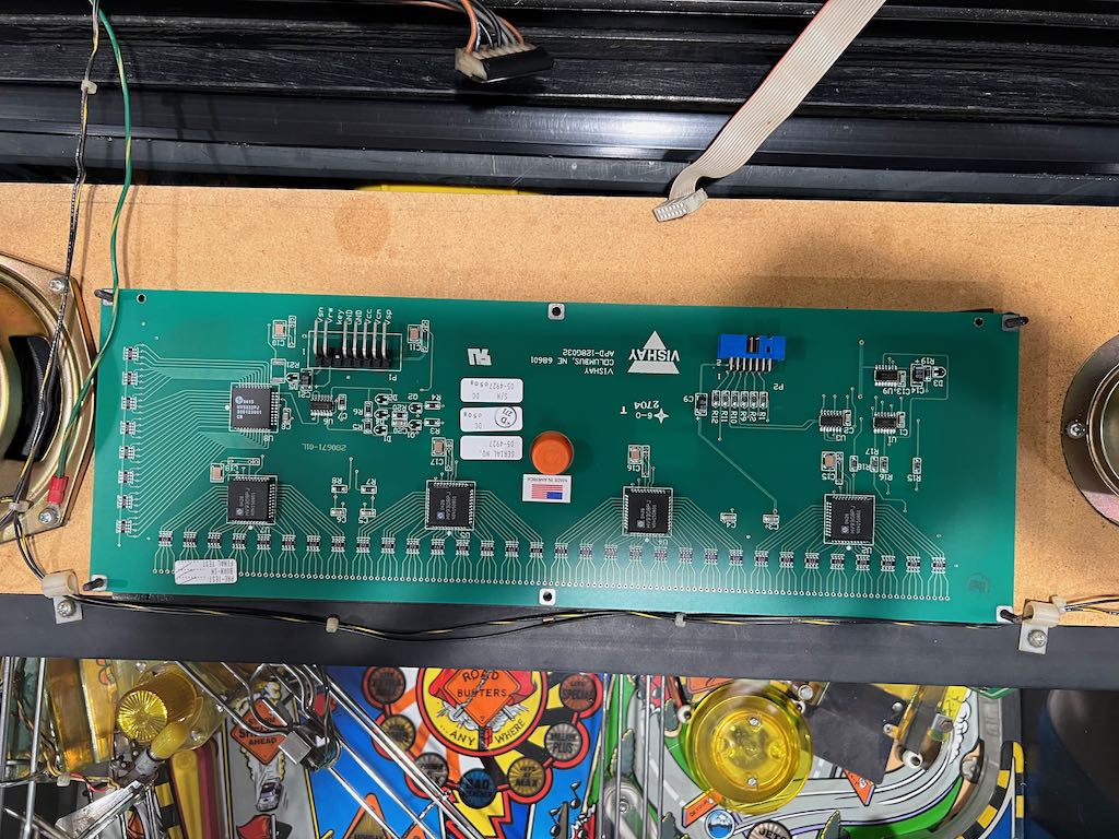
Lift up the cardboard to expose the DMD board. The cardboard might be a little sticky because it has been attached for so long. The exposed DMD is shown below.
Now lift out the DMD. Like the cardboard, it will likely be a little sticky. Just pull up and it will come out. When it is removed, it will expose 4 plastic posts on each of the corners as well as the see through plastic panel. See the image below.
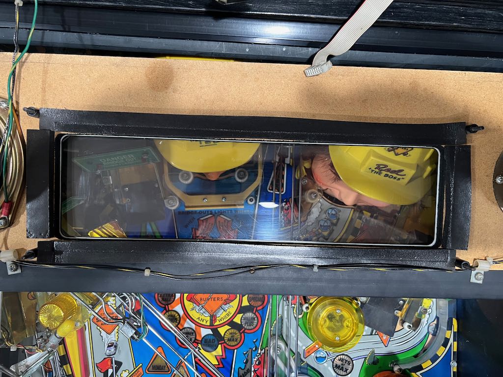
Use this time to clean the see through plastic panel. Consider some compressed air to blow out any little pieces of debris. You don't want to get everything back together and then see some junk on the clear plastic!
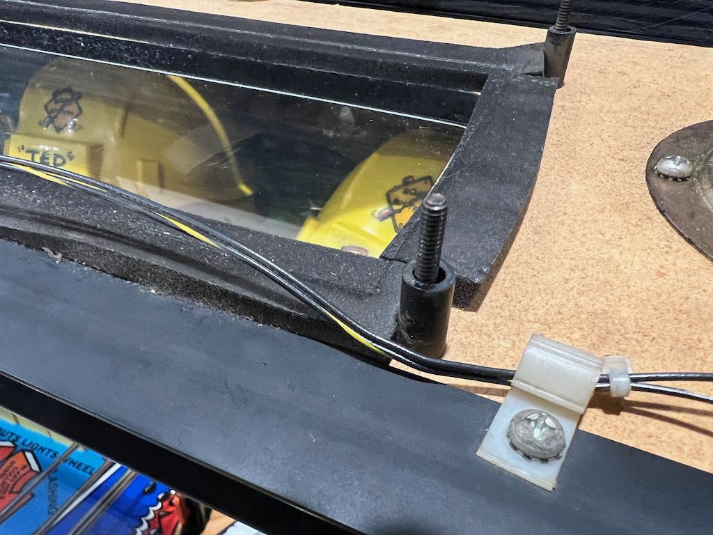
Below is a picture that shows the plastic posts more clearly.
Remove the plastic posts and replace them with the smaller white posts provided with the ColorDMD LCD kit. The white posts are shown below.
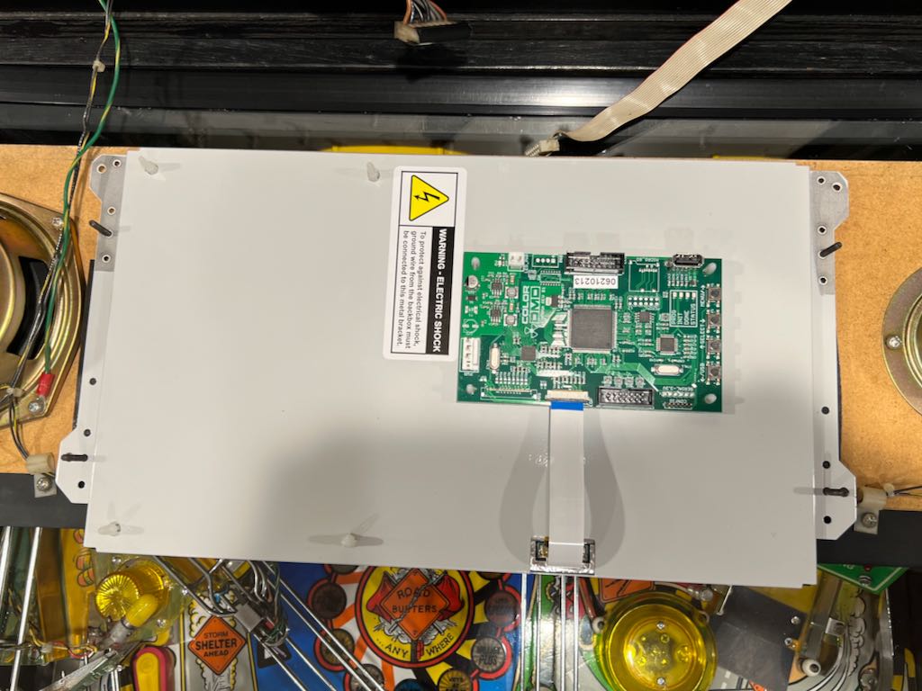
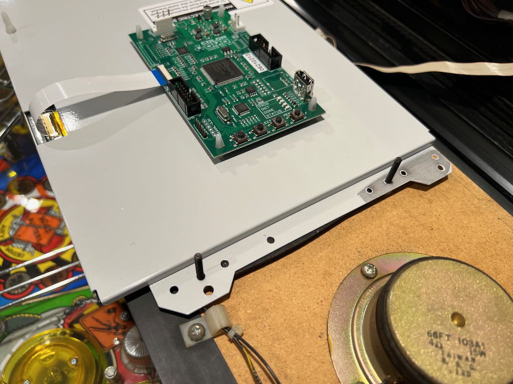
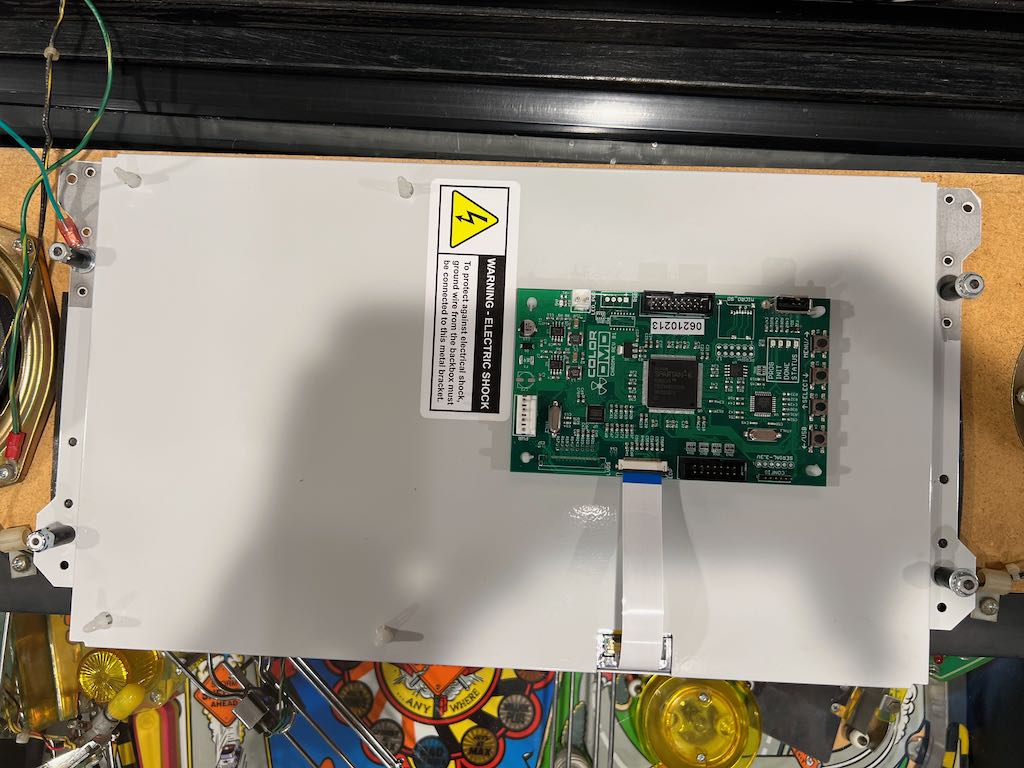
Now remove the ColorDMD LCD's protective screen cover and attach the ColorDMD LCD using the mounting holes shown below. The 2nd picture shows the mounting holes from a different angle.
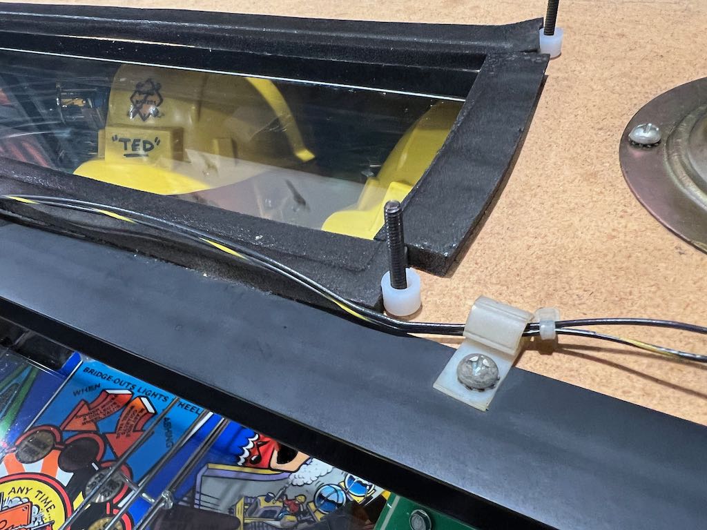
Place the ground cable that came with the ColorDMD LCD on the upper left screw post as shown below. Put the washer on top, then the black post that was originally there. Finally, use the original nut to hold everything in place. See the 2 pictures below.
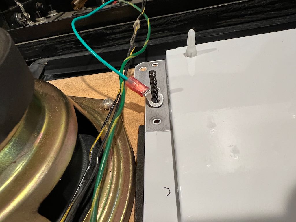
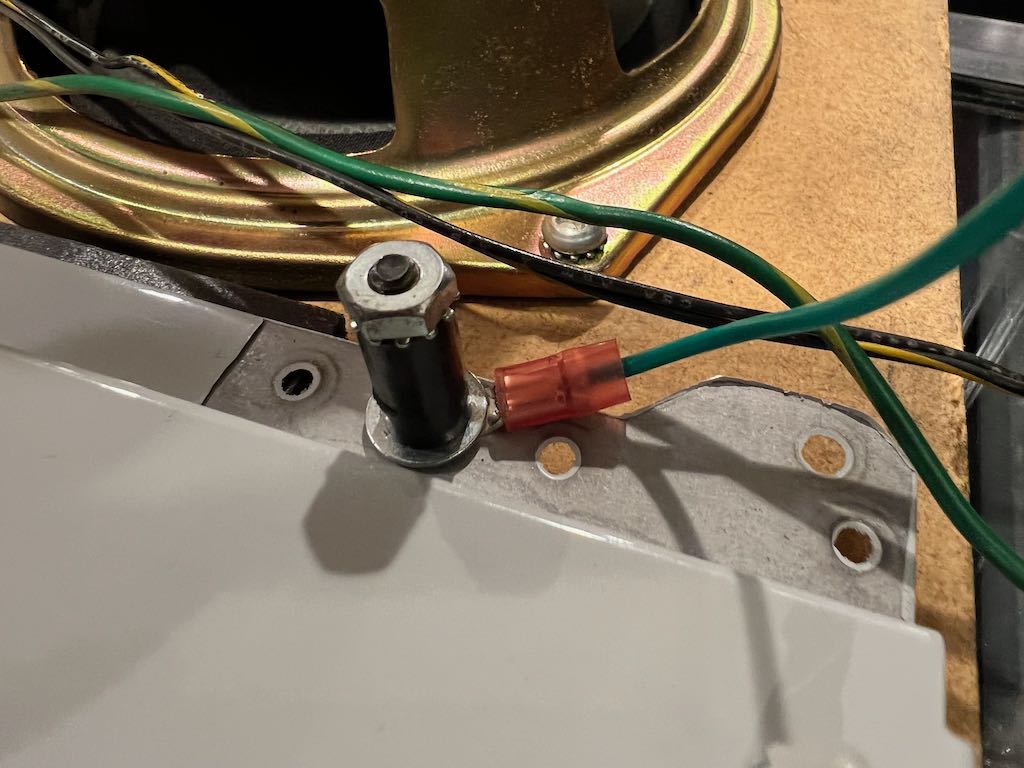
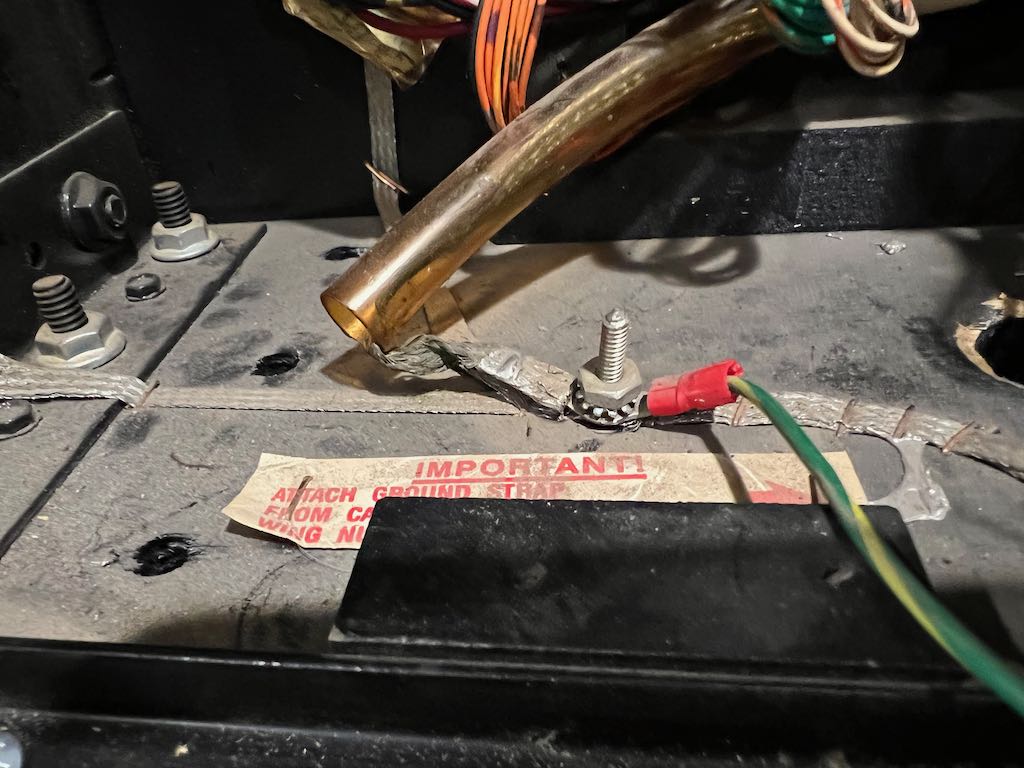
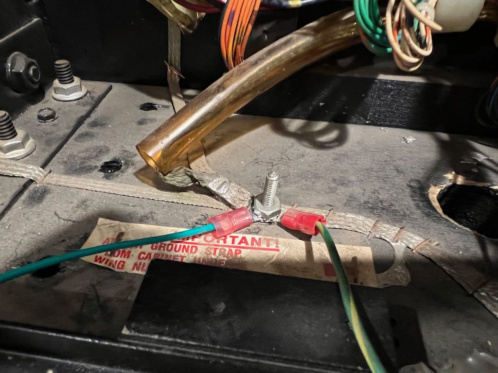
The other end of the ground cable connects to a ground screw on the bottom left of the backbox. Remove the nut, place the ground cable onto the screw post and attach the nut. The before and after pictures are below.
For the remaining 3 screw posts holding the ColorDMD in place, attach an original black plastic post, a washer and use the nut to hold it in place. These completed posts are shown below.
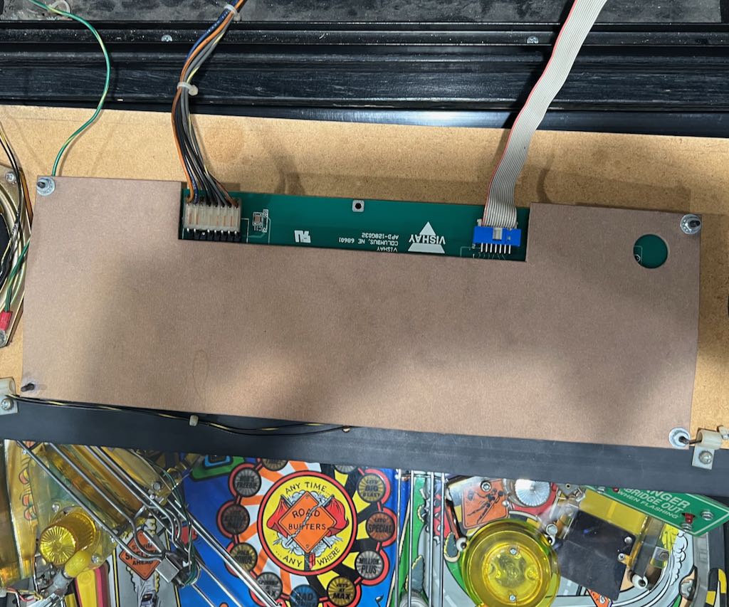
The next step is to connect the ColorDMD LCD power cable. It connects to J116 on the driver board. With Road Show, there is already a connector at J116. You can see this below.
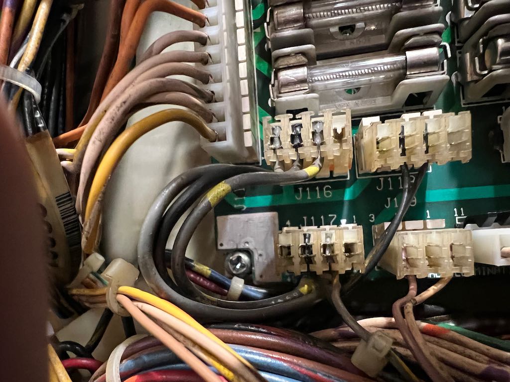
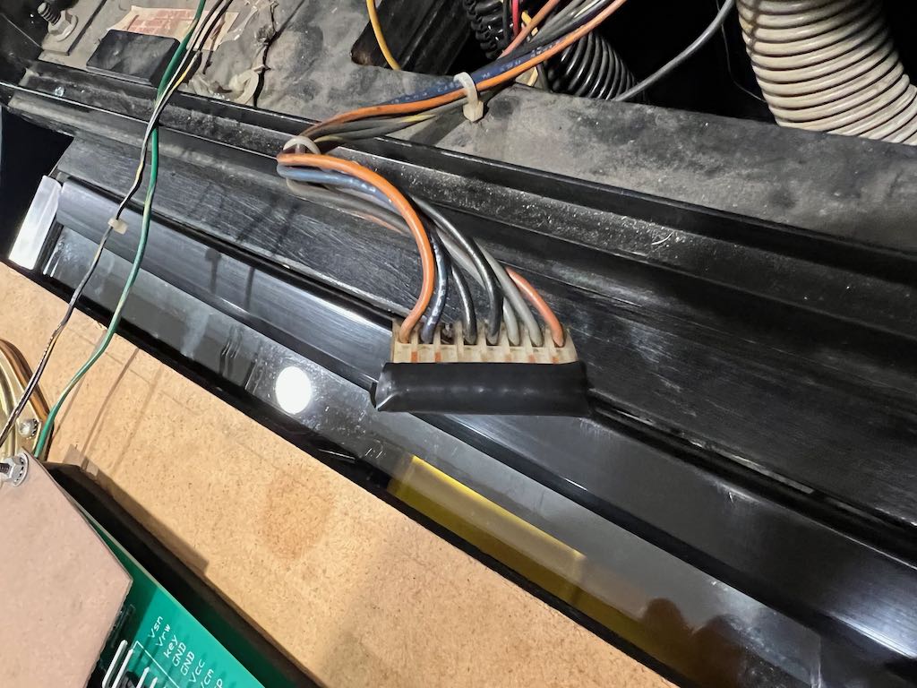
Because of this existing connector, we need to use the Z-connector on the ColorDMD power wire harness. Remove the existing cable from J116. Connect the ColorDMD LCD power cable to J116. Attach the Z-connector provided with the ColorDMD kit to the in-line connector and the attach the original J116 cable. This is shown below.
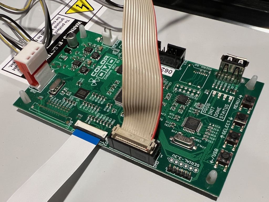
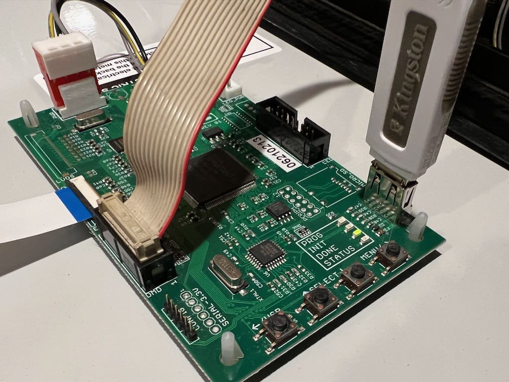
The other end of this cable must now be connected to the ColorDMD board. It connects to the connector labeled PWR. Also, the original signal cable must be connected to the ColorDMD board. This connects to the connector labeled DMD. While the power cable is keyed and cannot be connected the wrong direction, this is not the case with the signal cable! Notice the edge of the signal cable is red. Make sure you keep this orientation. The picture below shows these two cables connected.
Now power it up! You'll see the ColorDMD displaying the Road Show dots in gray scale and no colors.
Download the Road Show chroma.rom file and place it on a USB thumb drive. Connect the USB thumb drive to the ColorDMD LCD board.
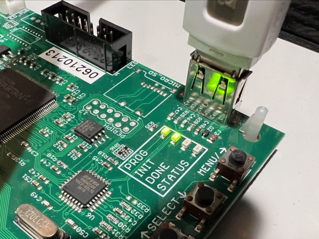
Now tell ColorDMD to upgrade to the chroma.rom. Hold down the button labeled "USB" for a few seconds and both the "PROG" and "INIT" lights should start flashing.
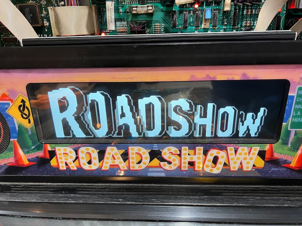
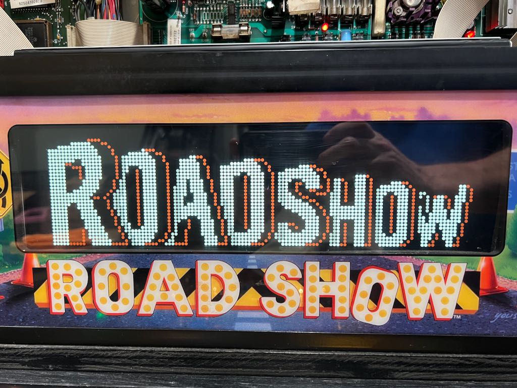
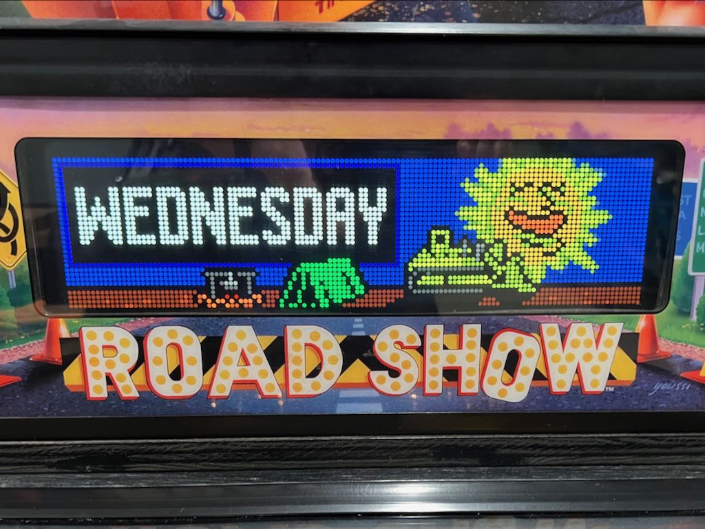
Now you have Color! Some pictures are below. I prefer to use the Dots XL mode.
Road Show was Resetting
Original 9/5/2011
A few months ago Road Show started resetting randomly while it was being played. While I haven't documented much of this, my Road Show had a tough life before it landed in its current happy home. The previous owner (owners?) had done all sorts of crazy things to it. One example is documented below where caps were added on the CPU power connector to, I assume, stabilize the 5V heading to the CPU board. I've done many of the "typical" tasks to resolve reset issues over the years, such as replacing several headers and caps. This made the game pretty solid.
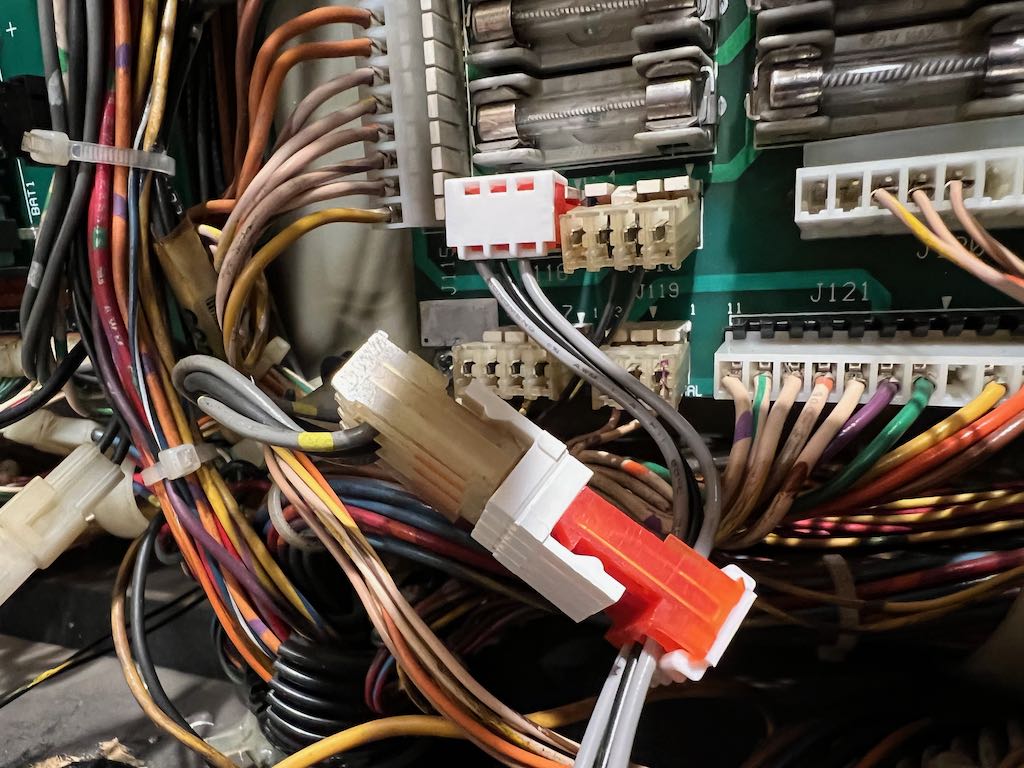
While investigating this most recent series of resets, I found that one of the diodes on the bottom left flipper had broken off. This is a well known cause for resets, so I was happy to have found it. I replaced the diode and play tested it for a while. Unfortunately, I eventually got another reset. I checked many typical causes, but found nothing wrong. Then I looked at the WPC-S voltage jumper.
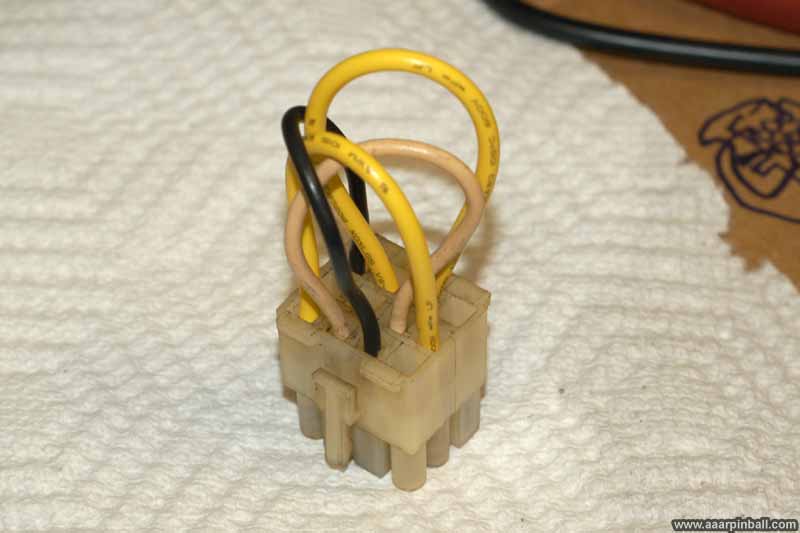
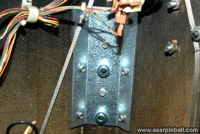
It's pretty ugly and is shown below. This game was imported back into the USA and someone did a pretty quick and dirty job of modifying the jumper wires to select USA voltage. While it's bad that wires were attached together with electrical tape, I found something even worse. The two connectors that needed to be moved to convert the game from 220V to 110V had the wrong size female molex connectors! They were too small. I suspect they never made very good contact at all.
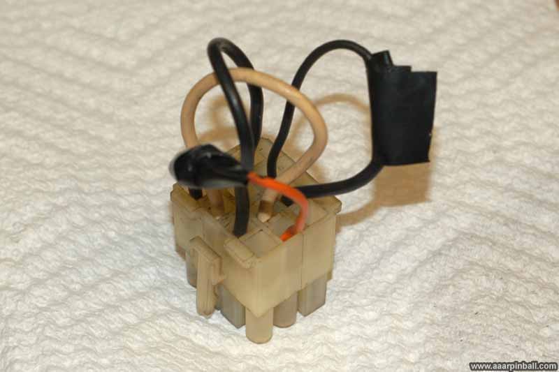
I rebuilt the connector using the appropriate 0.93 connectors. The improved version is shown below.
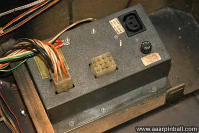
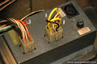
To be complete, the first picture below shows where the voltage selector connector attaches and the second shows it connected.
I hope this is the final solution to the resets. I've played several games since rebuilding the voltage connector and have had no trouble, but this is a problem that only time will tell if it is fixed.
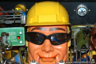
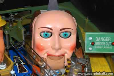
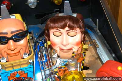
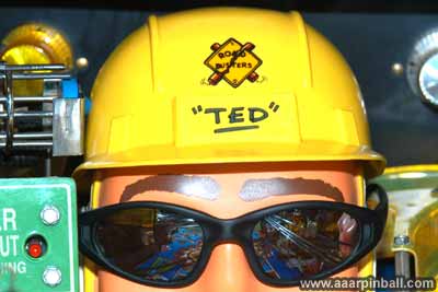
Ted has no eyes!
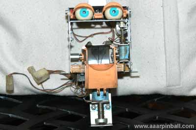
Poor Ted! He has no eyeballs. The good news is he has all the other appropriate equipment in his head (including eyelids).
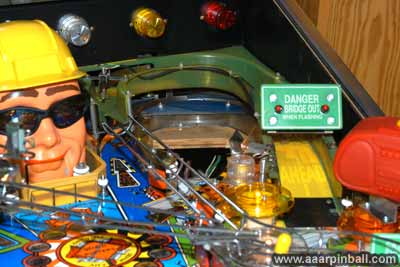
I've put sunglasses on him until I am able to find eyes. I'm quite happy with how the sunglasses look.
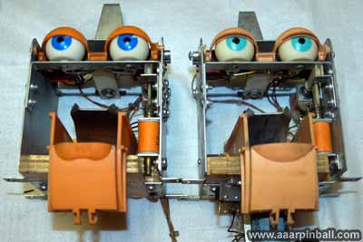
8/24/06 Update! I found eyes for Ted! These things are near impossible to find, but I lucked out. They are not NOS, but are in good shape. Below are two pictures of the eyes before cleaning. These are followed by the cleaned eyes. Looking good!
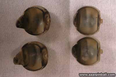
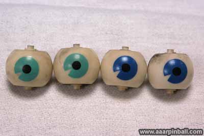
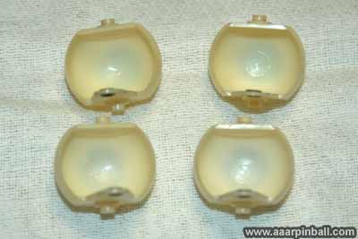
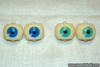
I haven't installed them yet. More to come.
How do you install Ted's eyes?
I'm sad to say it's much harder than you would expect. I understand the complexity of these pinball machines, but sometimes I wonder if the designers gave any though regarding the easy of repair. If Ted broke on location, I seriously doubt the operator would fix him. I needed to disassembly most of the rear playfield and then some parts below the playfield. The problem is that Ted's bulldozer must be disconnected prior to removing him from the playfield. Accessing these hex nuts basically requires removing the parts around him. Perhaps there is an easier way, but here are my notes.
- Under the playfield, disconnect the subway below Ted
- Remove the back/right plastic ramp from the top of the playfield
- Remove the long wire ramp from the back/left of the playfield
- Remove diverter from back/left plastic ramp
- Remove back/left plastic ramp
- Remove blue plastic pieces that are now visible (one is below the back/right ramp and the other is below the back/left ramp)
- Now you can access the bulldozer hex nuts. Remove them to separate Ted from the dozer.
- Under playfield, remove screws that hold bulldozer mechanism in place
- Under playfield, remove screws that hold Ted's jaw motor in place
- Below the playfield, the darn scoop is still in the way. Remove 3 of the 4 screws so you can slightly move the mechanism
- Below playfield, remove Ted's screws and take him out
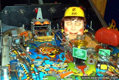
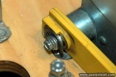
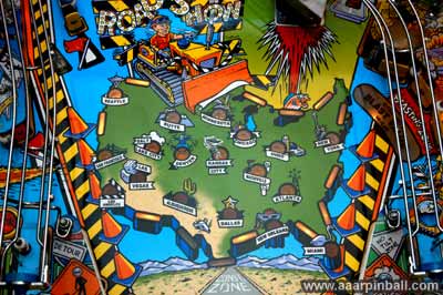
Below is a picture of the top playfield just before I removed Ted. The following picture shows the bulldozer hex nuts that must be removed.
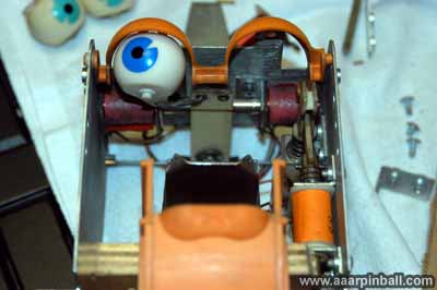
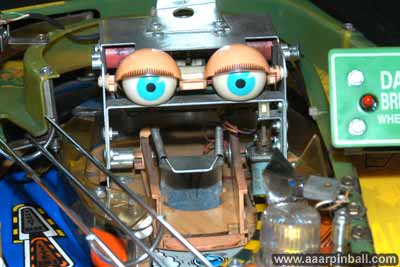
This following picture shows Ted with one eye almost installed!
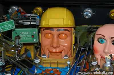
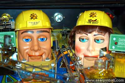
Finally, Ted can see Red. Here they are together, both out of the playfield and on the playfield. While having Ted's eyes working is great, I do miss the sunglasses a bit.
The knocker is missing!
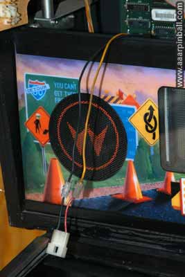
I wonder where it is? The picture below shows there once was a knocker, but only the screw holes remain.
I managed to find someone parting out a pinball machine and he sold me the knocker. Coincidentally, the pin he was parting out was a Road Show! When I went to install the knocker, I found something very strange. The connector that drives the knocker was rerouted down into the playfield cabinet! It then went out a hole drilled in the back of the cabinet. The two wires were hanging out this hole and not connected to anything!
I had noticed these wires when I first got Road Show, but somehow I had completely forgotten about them. Now I know it was some strange modification to the knocker. I wonder what a previous owner had connected externally that was triggered when the knocker fired?
The picture below shows the wire from the backbox that ran down into the cabinet and eventually out the hole drilled in the back. It is followed by a picture of the knocker I installed. Finally, a picture of the installed knocker is provided.
Ted's Mouth Did Not Open/Close Well
Ted's mouth did not open and close very quickly while talking. Also, it did not open very wide (unless you were shooting for multiball).
I was looking into this problem on and off for 2 months. Originally I hoped that a replacement motor would solve the problem. When I swapped Ted's motor with Rudy's (from FunHouse) and found the problem stayed with Ted (and Rudy worked as good as usual), I knew there was something non-trivial going on. To solve this problem I brushed up on my electronics and solicited help. A big thanks goes to Kinney B. and Martin from RGP. An extra big super thanks goes to Lee "you would be amazed what we did with LM339 ICs" J. for helping me with electronics theory, looking at the DMM readings I took, offering suggestions, and ultimately being fundamental to resolving this problem.
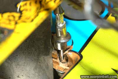
I disassembled Ted's motor mechanism so the motor could spin without moving the gears. This allowed it to continue to spin in a single direction without the "sector" gear reaching its limit. After much measuring with the DMM on the "Dual H-Drive Motor Controller Board Assembly", the investigation lead to transistor Q6, a TIP102. Between the collector and the emitter the DMM measured only 7V when Ted's mouth was running in the open direction. This seemed odd and Lee suggested I replace the transistor. I had previously tested all the transistors using the diode method so often mentioned on R.G.P. and Clay's site. I placed the DMM in diode mode, put the black lead on the metal tab and the red lead on the transistor's outside leads. The DMM returned ratings in the 0.4 to 0.6 range, which is the good range. Now, Clay goes on to say that this test is not guaranteed to be accurate in all cases. I would find out it certainly wasn't accurate for me! Please keep this in mind when you check transistors!
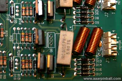
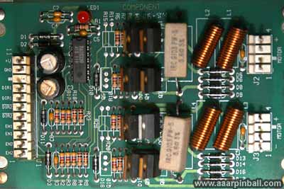
The first picture below shows what the PCB looked like after I removed transistor Q6. The second picture shows the newly installed TIP102 transistor in the Q6 position. It is the one with the shiny tab in the middle/bottom. This was the first time I desoldered a transistor and soldered in a new one. I'm quite happy with the results.
After I replaced Q6, I reinstalled the PCB, connected the wires, crossed my fingers, and turned on Road Show. Nothing smoked or popped. I went into the test menu and tried out Ted with the motor mechanism still disassembled. The motor looked to be spinning the same rate in both directions. I assembled the motor mechanism, lowered the playfield and started a game. Replacing transistor Q6 made all the difference in the world! Ted's mouth no longer looked like he was mumbling! It now opened (quickly) as well as made quick smaller motions. Yeah!
I pulled out the DMM and tested the voltage on Q6. What previously read as 7V was now reading as 12V! All fixed. It appears that transistor Q6 was never turning off completely and causing the voltage across the motor to be smaller than expected.
(Keep in mind that the schematic has errors on it! I'll see about providing this information later.)
Chip in playfield below "Blasting Zone" bumper post
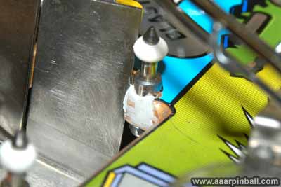
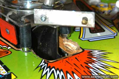
When I was replacing the rubber rings on the bumper posts, I found that the leftmost bumper post in the "Blasting Zone" area wobbled back and forth. This post is shown in the picture below. It is the post that is leaning towards the left, at the left of the picture, and does not have a rubber ring.
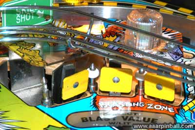
When I examined the post from the back, I found the playfield had chipped away below a good portion of the post. This can be seen below.
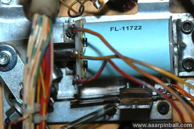
I suspect this damage occurred because some bozo who owned this Road Show previously had replaced the middle left flipper coil with the wrong strength. The manual states this coil should be a FL-11722, which is the second weakest coil, but a FL-11629 was installed, which is the strongest coil possible! With this incorrect coil, all shots at the "Blasting Zone" from the middle left flipper were too forceful, would often hit the bumper post, and caused the crack.
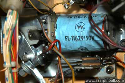
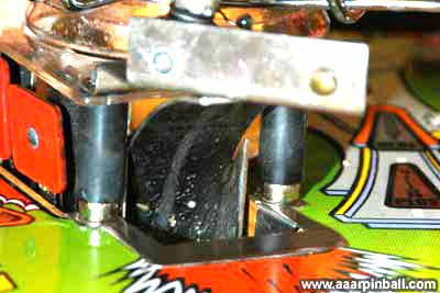
I've replaced the flipper coil with the appropriate strength, as shown below. It's too bad the coils purchased from Marco do not have the traditional Williams coloring scheme. The FL-11722 is traditionally green.
I used JB Weld "Waterweld" to repair the playfield chip. Waterweld comes in a tube and is a putty. I cut a small amount from the tube, rolled it between my fingers until it turned a solid gray color, and then pressed and molded it into the chip. I used the round (top part) of a drill bit, with the same diameter as the bumper post, to ensure the hole for the bumper post was not filled in by the putty. After about an hour, I sanded it with 120 grit. The picture below shows the results. It appears very strong.
The close up above makes my work look a little sloppier than I thought, but it's not visible to the player. Here is the final result from the front.

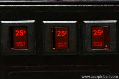
Coin door had non-USA or missing inserts
I created my own inserts and placed them in the coin acceptors. The center coin acceptor had been glued closed, but lucky I was able to pop the glue out using a Phillips screwdriver. The picture on the left shows the original and the picture on the right shows the cleaned up version,
Below is the insert I created. Simply printing it on normal printer paper works great! I found no need to use any special paper at all.

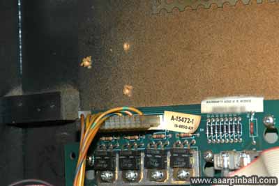
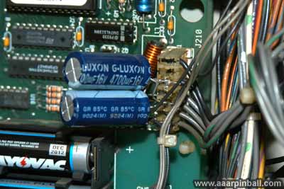
Big capacitors connected to the WPC-S board?
The image below shows the capacitors that have been attached to the WPC-S board. I'm not sure what purpose they serve. Maybe to assist with power fluctuations?
Road Show needed a ROM upgrade
This was solved easily enough. The Road Show originally had the LX-3 ROM. I've upgraded it with the L-6 ROM.
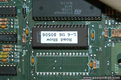
Road Show was also configured for a European mode. For example, it displayed euros. I changed the dip switch settings to place it in U.S.A mode.
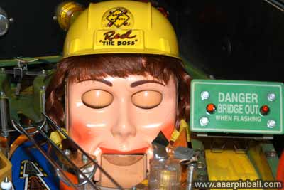
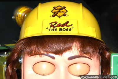
Yiikes! No Hair! No Hat!
Red looks much better in this picture than she did when I first brought her home. I've given her a good cleaning. Prior to this she was grubby and had double stick tape around the top of her head (even though she had no hair!).
She now has the appropriate hair as well as a construction hat.
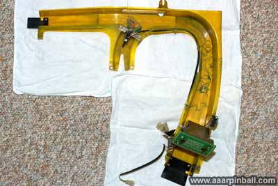
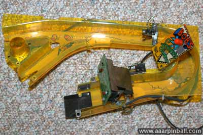
Right ramp was dirty!
I did not realize how dirty the ramp was until I took it off. Here is a picture of the dirty ramp followed by a picture of the cleaned ramp.
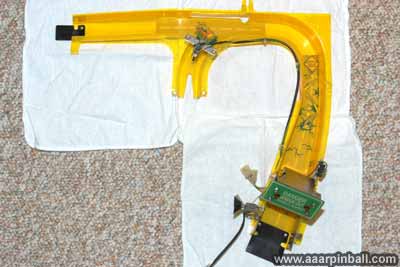
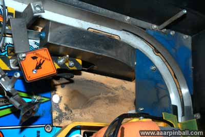
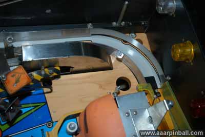
The two pictures below show the location on the playfield where the right ramp is placed. Both of these pictures were taken before I cleaned the areas.
Left ramp was dirty also!
I removed the ramp and cleaned it. This required removing the large wire frame ramp that is mounted on top of the left ramp. Below is an image of the dirty left ramp followed by an image of the cleaned version. Big difference!
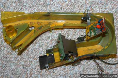
Here is an image that shows the playfield below the ramp. It was also quite dirty. The cleaned up playfield is visible in the 2nd picture below.
Radio was missing.
The Radio on top of the pop bumper was missing. Before I realized NOS is reasonably easy to acquire, I purchased one from a Road Show that had been parted out.
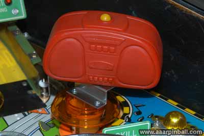
With some scrubbing, it cleaned up well.
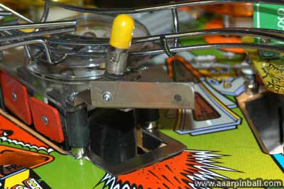
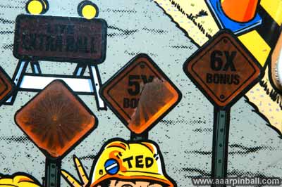
Missing Start City Event sign.
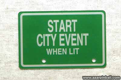
I purchased a reproduction sign. It's very high quality although the green color is darker than the other plastics. Below is a picture showing the missing sign.
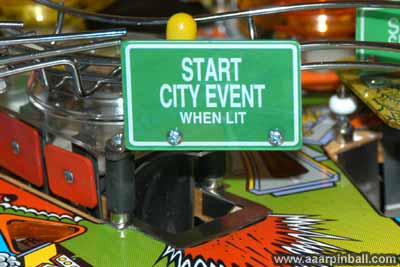
Here is a picture of the reproduction sign as well as the playfield with the sign installed. I used screws with nuts to attach the sign instead of the original rivets.
Hole wear around "City Start"
The pictures below show the wear around the "City Start" hole.
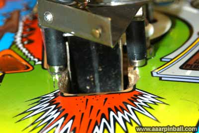
I've purchased a "hole protector" and installed it.
 .
.
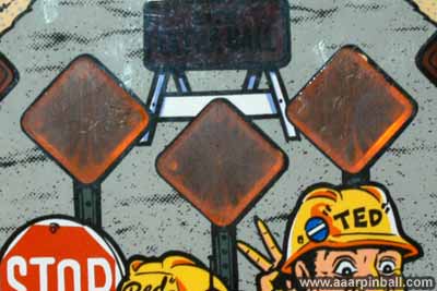
Some of the inserts have chipped away
Working on this...
I decided that no decal would look better than a ripped decal, so I removed the ripped decals.
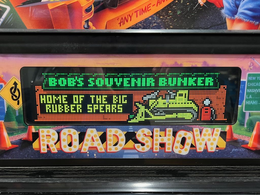
"Bob's Souvenir Bunker" sign is cracked in half
A previous owner had attached the two halves with a nylon cable tie.
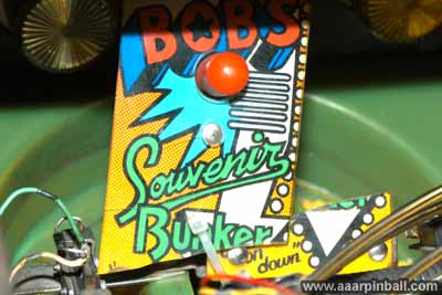
I was able to super glue the halves together. See below.
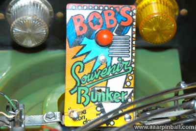
Crud! It broke off again while I was cleaning it. I've tried the super glue one more time and I'm keeping my fingers crossed that it will hold.
Wires had broken from solder connections
Several wires had broken and needed to be soldered.
The image above shows the EOS wires that needed to be soldered.
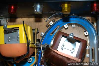
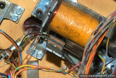
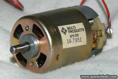
Shaker motor was not working
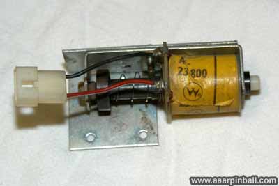
I ordered a replacement shaker motor and found out that it didn't fit the mounting hardware! Below is the original motor.
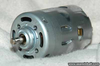
Below is the "replacement" motor. Both apparently have the same part number. The images show that the protrusion surrounding the axle is a different shape and size.
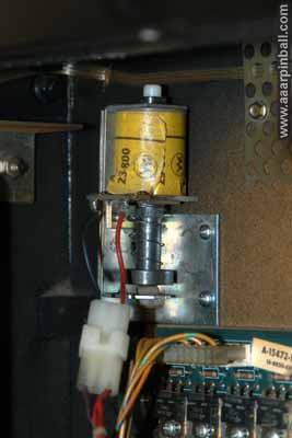
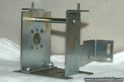
The image below shows the shaker motor mounting hardware followed by a picture of the motor in the mounting.
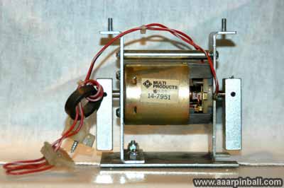
I'm not 100% sure what I did to get my shaker motor working, but it's working perfectly now. When I disassembled the assembly and manually spun the motor (by hand), a bunch of junk fell out. It was like small metal flakes. When it was reassembled, it worked just fine. I also checked the brushes and found them to be in very good condition.
Red's eyes and eyelids didn't work
I took Red apart and found out that the wires to the eyeball solenoids were broken off. After soldering these back, Red's eyes were able to move left and right.
Her eyelids, however, would not stay open. The eyelid solenoid no longer worked and the eyelid plunger assembly was broken. I was able to successfully super glue the plunger back together. After installing a new eyelid solenoid, Red's eyelids now function perfectly.
Dot Matrix Display has horizontal lines
When the DMD displays horizontal lines, parts of the lines are missing. However, when it is displays vertical lines, they are completely there. I don't think the DMD had "out gassed" because the individual dots turn on (sometimes). Also, when the test menu performs the "turn on all dots" they all turn on. I took this DMD and placed it in my Getaway and it had the exact same problem. I placed the dot matrix display form Getaway into Road Show and it worked great. I concluded that the Road Show PCB's were working fine and the problem was with the DMD display itself.
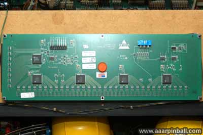
I ended up purchasing a brand new DMD. Below is a picture of the back of the new DMD.
Ted had no stickers on his hat and Red's stickers were grubby.
I scanned the stickers and cleaned them up! I created 300 DPI images and printed them onto clear mailing labels. The results are excellent. Below are the stickers I created.


Drop me a note if you would like a high resolution version of the above graphics. Here is a picture of Ted's hat and Red's hat with the new decals.
The threads in the leg bolt plates were stripped!
Wow! This made it a major pain to take the legs off. A previous owner had used nuts on the inside of the bolts in the cabinet to hold the legs in place. I had to have one hand inside the cabinet with a wrench and the other hand outside the cabinet with a ratchet. All this while it was raining and I was trying to get the pin into a van...
I purchased 4 new leg bolt plates and replaced the originals. The solution was simple yet removing the old bolt plates and installing the new ones was a hassle. The picture below is one of the new leg bolt plates. There is no need for nuts on the inside any more.
Playfield had Mylar...
The Mylar was cloudy and dingy. Using the freeze method, I was able to completely remove the old Mylar. The playfield was almost completely covered with Mylar, yet it came off with little problem at all. It took a good hour or so after to scrape off all the glue residue, but the results were fantastic.
Why do I believe my Road Show was from Croatia?...
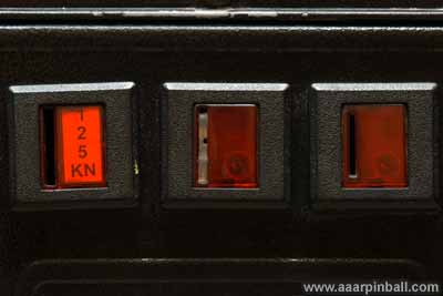
I know it was an import. Also, I found the following coins in the cabinet. This is certainly not 100% conclusive, but it's good enough for me.
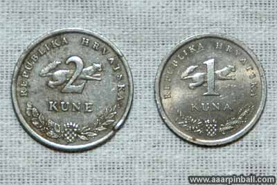
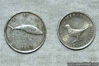
The Kune is official currency of Croatia.