Williams Star Trek: The Next Generation Pinball
Repairs, Restorations, Tweaks and Insights
Introduction
STTNG was not a pin on my list of favorites or even one that I was looking for. Truth be told, I had played it once before and had not been overwhelmingly impressed. In retrospect, I believe the one I played wasn't operating correctly. While a poorly maintained STTNG may be no fun, a working STTNG is a great game!
When a STTNG became available locally, I decided to seriously consider purchasing this pin. It was not shopped, but was functional. It appeared to have the ability to clean up very well. I decided to go ahead with it ... and I'm very happy I did!
Below is an informal list of the problems I've encountered and some various pictures.
Tell me about this game!
Here are what I consider to be the unique aspects of STTNG
-
Two cannons that shoot the pinball at targets or up the ramps.
-
Really cool multiball. You are fighting the Borg spaceship!
-
This game has three separate vertical up-kickers.
-
Three ramps (Alpha quadrant, Beta quadrant, and Delta quadrant).
-
Player control! At various points in the game, such as launching the ball, the player gets to select what happens.
-
Cool initial ball launch wire ramp. This is the one with the circle at the end.
-
It's a widebody.
Just what is the machine doing when I turn it on?
STTNG is a 6 ball game. When you first turn it on, the machine ensures that 3 of the six balls are staged below the playfield. This is what causes it to launch balls and seem to disappear below the Borg ship. One ball ends up underneath the left cannon VUK, one below the right cannon VUK, and finally the third ball goes below the left VUK that kicks the ball onto the leftmost wire ramp. Staging these balls requires the subway diverters below the playfield to operate, as well as the semi-hidden drop target below the Borg ship.
In order for the balls to drop below the playfield, the drop target must work. The pin will trigger a solenoid to drop the target, but if it the target doesn't drop down then the ball will hit it, bounce back, and roll down the playfield to the drain. The ball will not be staged correctly. The CPU will try again, however. If you are lucky, this first impact will have caused the drop target to drop and when the pin fires the ball again, the balls will stage correctly. Still, your drop target will be problematic ... but you can at least play!
My battery was inserted upside down for a year and a half!
One weekend I got a brick of AA batteries and started to replace all the batteries in my pins. It was uneventful ...except for STTNG. When I went to remove the old batteries, I noticed the rightmost (as you are looking at the board from the playfield) battery was upside down! The first two had the + on the top while the3rd had the + on the bottom.
I scratched my head since STTNG has been working fine and has kept all settings. Additionally, it has not received a lot of play recently. These batteries have been in there for about 16 months!
I used a volt meter and measured the incorrectly placed battery's voltage. It showed new battery voltage, about 1.67V. I measured the two correctly placed batteries. They were down to about 1.53V. I replaced all 3 and ensured the 3rd one was inserted correctly this time. Pin is working fine --- no settings have been lost.
I think the AA batteries in the WPC are in series. With normal battery placement, we would have 1.5 + 1.5 + 1.5 = 4.5V (assuming a battery has 1.5V). When a battery is in backward, I guess you get 1.5 + 1.5 + (-1.5) = 1.5V. I did a quick test and this was the voltage reading I got.
So in conclusion, the battery backed up memory on my STTNG can operate with only ~1.5V . Very odd!
My STTNG tells me the Cannon cannot find home yet it works in test mode!
STING lies to you! Sad but true. One would hope that diagnostics would be accurate, but they are not always. While it certainly can be the case that the cannon is unable to find home because of some problem with the home switch, it is also completely possible that the problem has nothing to do with finding home.
Here is the problem: STTNG prioritizes shooting a ball from a cannon over other tasks when it thinks the ball shouldn't be in the cannon. When the pin boots up, it tests the cannons by swinging them out and back. If there is a ball in the cannon, when the cannon swings out past "mark" the ball is fired from the cannon and the cannon eventually swings back to home. However, if home is reached when a ball is in the cannon, the cannon swings out again! At boot time the software only lets the cannon swing out and back a few times and then decides that "home" cannot be found. It seems to assume that swinging out and back multiple times is always a result of the inability to find home.
But why would it keep swinging out and back if the game fires the ball when the cannon has swung out? In my situation the opto that tells the CPU whether a ball is loaded in the cannon wasn't getting power. This caused the CPU to think there was always a ball in the cannon --- even if there wasn't! This is what caused STING to lie to me and say that home could not be found. Note that while I have not experienced this myself, I suspect the same result will occur if the solenoid is broke and doesn't fire the pinball. Again, this would keep the ball in the cannon.
You caught my interest. What's this "home" and "mark" stuff?
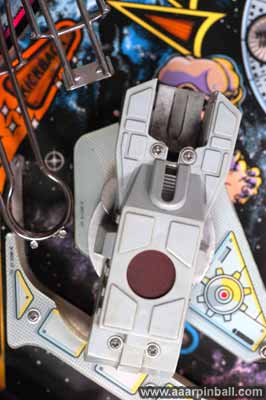
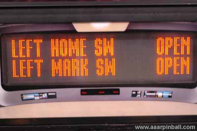
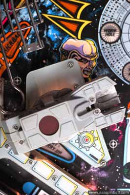
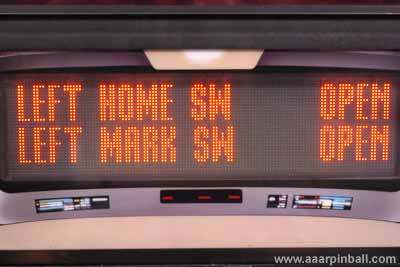
The "home" switch indicates when the cannon is in its standard position. This is the position where the wire ramp feeds a ball into the cannon. For the left cannon, this is when the cannon is furthest to the left. For the right cannon, this is when the cannon is furthest right. When at home, the home switch is CLOSED, otherwise it is OPEN. The two pictures below show the left cannon at its home position and at the position where it is no longer considered at home. Below each picture is the diagnostic showing the state of home and mark. Notice the second picture shows the cannon only slightly turned toward the right.
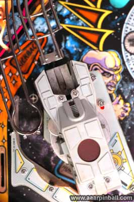
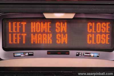
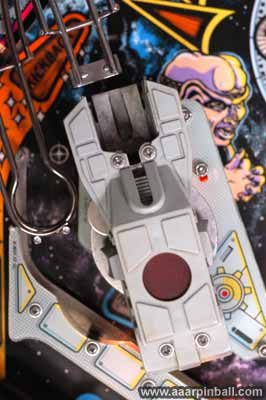
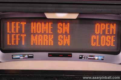
The "mark" switch indicates when it is ok to fire the cannon and release the pinball. This occurs when the cannon has swung out further from home. The mark is useful because it provides STTNG the ability to ensure you do not fire the cannon when the cannon is in front of the wire ramp or other unwanted object. If the cannon is past mark then the mark switch is OPEN, otherwise it is CLOSED. The first picture below shows the position of the left cannon when mark has been reached and the player is allowed to fire the pinball. The second picture simply shows the rightmost swing of the left cannon. The diagnostic switch information is shown below each picture.
Explain how that Drop Target works!
When my drop target wasn't working correctly, it was hard to tell exactly what was wrong because I didn't know the drop target's correct behavior. Now that my machine is working correctly, here is what I found to be the correct drop target behavior. When you first launch a ball, the drop target should be in the down position for the modes that follow.
-
Launch Probe
-
Ball Lock
-
Start Mission
-
Skill Shot
The drop target should be in the up position for the following mode.
-
Warp Factor 4
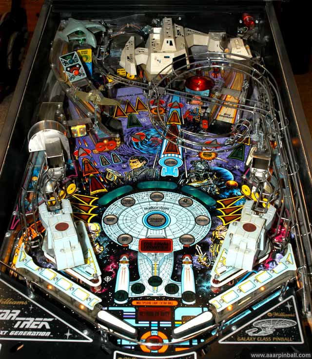
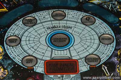
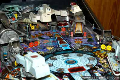
Playfield
Here is an image of the playfield.
General Illumination (G.I.) strand wasn't working
I dug around trying to solve this problem longer than I care to tell. I started looking at triacs, drivers, transistors, and everything else. In the end, I found it was a fuse that was blown. While the first thing I did when trying to solve this problem was to check the fuse, I ended up checked the wrong one! I checked F110 when I should have checked F109. Replacing F109 solved the problem.
More G.I. Problems
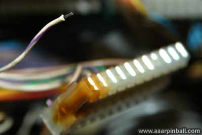
I noticed that some of the G.I. lights on the playfield were not working. I went into diagnostics and found out G.I. string #5 wasn't lighting at all. I was going to check fuse F106, but in doing so I noticed J121 was burnt! I put my finger on the burnt spot and it was hot! Look at the picture below to see the burnt connector.
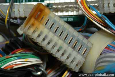
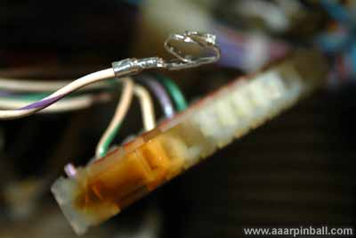
I was very surprised to see this burnt connector because I had checked this connector when I first brought the machine home. It was fine back then. When I checked F106, I found it was bad. This wasn't surprising given the burnt connector. I decided to rebuild connector using trifurcon connectors. The first picture below shows a wire I cut from the burnt connector and stripped. The second picture shows the crimped trifurcon connector.
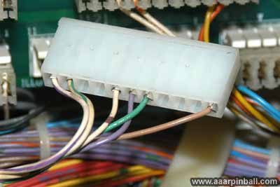
Below is the rebuilt connector. It appears to be upside down, compared to the original. By this I mean the rectangular slots associated with each pin on the connector are on the bottom (rather than the top) when plugged into the driver board. It wouldn't fit the other way, so I assume this is correct.
I replaced the fuse, plugged in the connector, turned on the machine and ... the G.I. bulbs on string #5 were very dim. I suspected I had a short in the G.I. string, which caused the connector to heat up and the fuse to blow. After an hour or checking all the bulbs on this G.I. strand, I found the problem. The lamp base below the left cannon had a bent connector. This connector was pushing up against the other connector and causing the short. I suspect I did then when I disassembled the left side of the playfield! This explains why the connector had not been burnt when I checked it initially. The fix was easy ... bend the lead back.
I crossed my fingers, turned on the machine, and found G.I. strand #5 is alive and working well.
Weak Flippers
The lower left flipper was extremely weak. It could not even hit the ball up the beta quadrant ramp. The lower right flipper was somewhat weak. It wasn't horrible, but it didn't feel right. The upper right flipper was also weak which made it very difficult to it the ball up the delta quadrant ramp. This flipper was also missing one of the two diodes and a previous owner had unwrapped the coil a bit. Here is a picture.
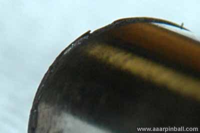
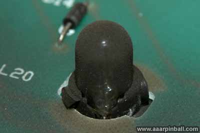
What was the solution to all these problems? Rebuild all three flippers! I completely rebuilt the bottom two flippers, but I didn't have a new plunger for the upper right flipper. The bottom two worked perfectly after rebuilding. New blue coils are way strong. Even though the upper right flipper got a new coil, the flipper was sticking after being triggered. It would slowly go back to home. It wasn't a spring problem. After I got a new plunger, I looked closer at the old one. The end was bent up around the side the strikes the stop bracket! This apparently was causing unwanted friction against the coil sleeve. Here is an extreme close-up of the damage. It should be smooth, but the end has mushroomed out.
Replacing the plunger fixed the problem. Now the upper right flipper works as perfectly as the bottom two. Here is a picture of the final results.
Spinner Target did not Register
This was the first problem I noticed when I got the machine home and started using it. Using a DMM I found that no voltage was going to the spinner target's switch. It turned out to be related to another problem. See below.
Pin reported that I should check the EOS switches
After several games, the pin started reporting that the EOS switches should be checked (in addition to the spinner target switch). It turns out the spinner target and the EOS switches are all "flipper grounded" switches. After examining the flippers, I noticed a wire was broken off the mechanism for the upper right flipper. The first picture below shows the broken wire and the second shows the repaired wire.
After the repair, the EOS switches worked correct as well as the spinner target.
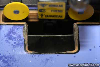
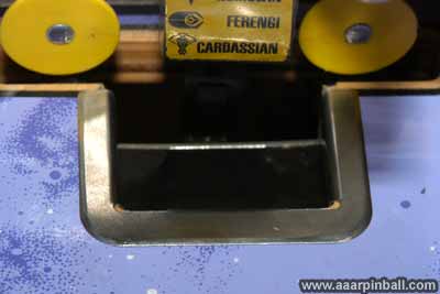
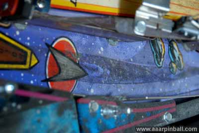
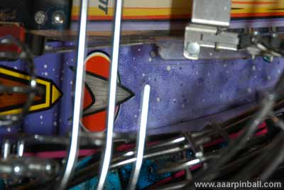
Neutral Zone Wear
The Neutral Zone had some significant wear. This is a very common issue and luckily a STTNG hole protector exists. The left picture shows the wear spot and the right picture shows the hole protector installed.
Dirty Dirty Dirty
This pin was dirty! The guy I purchased it from though it had been stored somewhere without the playfield glass. Here are some dirt pictures.
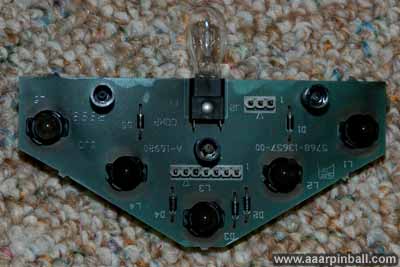
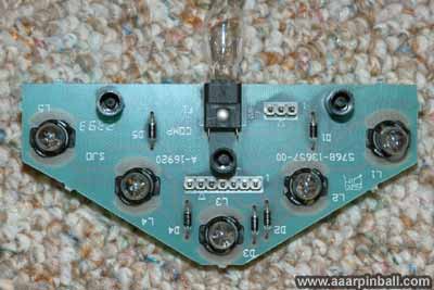
The lamp PCBs were dirty also. Below is a before and after image.
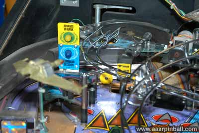
Here is a picture of the area to the right of the Beta quadrant. This is where the ball goes when the player pulls the gun trigger. The first picture is before cleaning and the second is after.
Wire Ramps Removed
Anything look funny in this picture? You guessed it... the wire ramps have been removed. It shouldn't have been too hard to guess (given the title of this section!). I removed the wire ramps while cleaning the playfield.
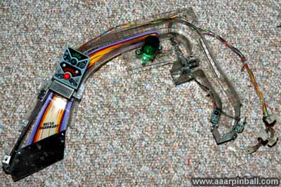
Delta Quadrant Removed
Below is a picture of the playfield with the Delta Quadrant ramp removed. It is followed by a picture of the ramp disconnected from the playfield.
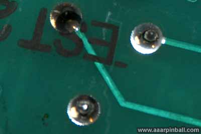
Lamp PCBs had Broken Solder Connections
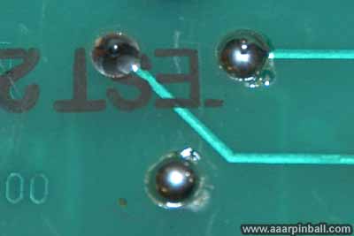
Even after replacing the bulbs, many lamps did not work. It turns out the solder connections for several of the lamp bases had gone bad. It's a bit difficult to tell from the picture, but the first picture below shows one of the bad solder connections. Look at the upper right solder connection. It had broken away from the other solder in a circular pattern. The center had separated from the outside. The second picture shows the repair.
Cannon Trouble
I experienced two separate problems with the cannons.
-
The right cannon would not fire the ball when the trigger was pulled although the sound effect would occur. The cannon would fire, however, when it turned counter clockwise all the way.
-
The left cannon fired the ball just fine, but after firing the ball it would continue to trigger the solenoid two or three more times!
Both of these problems were tracked down to failing wires in the cannon harness. There was no problem with the home and mark adjustments. Cannon harness problems are very common for STTNG.
For the right cannon, the wires going to the solenoid were going bad. A good connection was only made when the cannon had swung out all the way. For the left cannon, the opto that tells the CPU whether a pinball is in the cannon had a flaky wire. I was able to test this using the diagnostics. With the cannon at home and no ball in the firing chamber, I checked what the switch was reading using the diagnostics. It stated that no ball was present. I then used the solenoid test menu to swing out the left cannon. After doing this, I went back to the switch tests. Now the cannon registered as having a pinball in the firing chamber! This explained why the CPU would keep firing the solenoid.
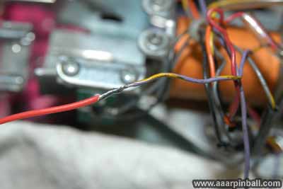
I replaced a section of all 4 wires (two going to the left cannon's ball opto and two going to the right cannon's solenoid). The section I replaced was the part that moves when the cannon moves. I cut the wire a few inches from the connector on the top of the playfield (either the opto or the solenoid) and a few inches from the connector below the playfield. I then twisted on a new piece of wire to the old, soldered, and put on shrink tubing. The first picture below shows the two wires cut from the left cannon's opto. The second picture shows new wire twisted onto the old wire for the right cannon's solenoid. Sorry... I don't have a picture of the final shrink tubing. As you can see, I used red wire (20 gauge). I would have liked to use the original coloring, but I didn't have that color wire available.
Both problems have been resolved. For what it's worth, it's pretty obvious a previous owner had to perform the same surgery sometime in the past.
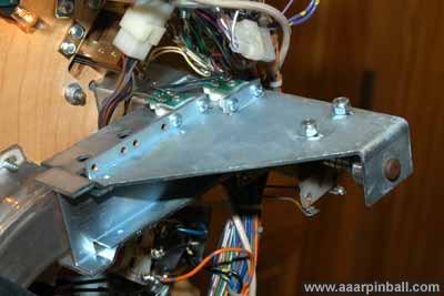
For completeness, here is a picture of the below playfield mechanism that makes the cannon work.
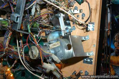
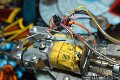
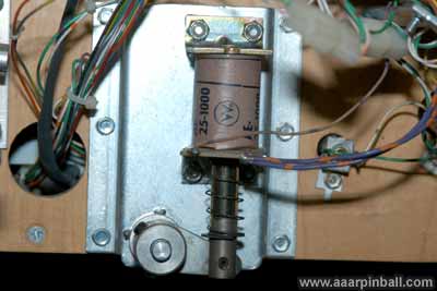
Drop Target Wouldn't Drop Automatically
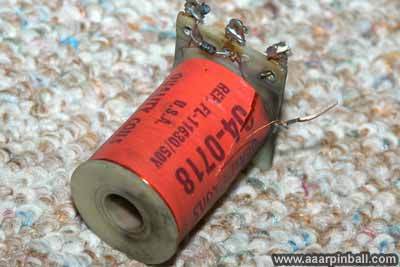
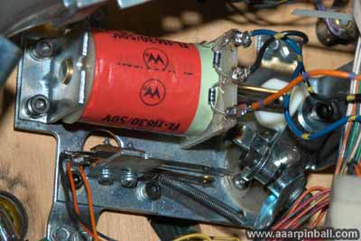
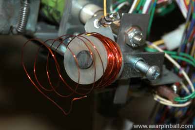
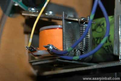
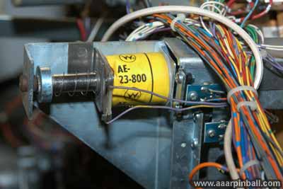
The drop target hidden below the Borg ship would not drop when commanded by the CPU. It would drop when the ball hit it, but not automatically. It turns out that the sm1-26-600 coil that causes the target to drop was fried. This coil quickly fell apart when I was checking its operation. See the picture below.
I must have angered the broken coil because after determining it was bad, fuse F103 would blow every time I turned on the machine! At first I was puzzled because I didn't realize that F103 had blown. Rather, the visible effect was that the pin was unable to stage the 3 balls below the playfield. When F103 goes, the diverters below the playfield stop working. After determining there was a connection between F103 blowing and the drop target coil, I ended up disconnecting the sm1-26-600 coil completely from the machine. This kept the fuse from blowing until a new sm1-26-600 coil arrived. I blew up 3 F103 fuses (3A 250V Slow Blow) trying to figure this out.
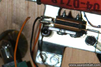
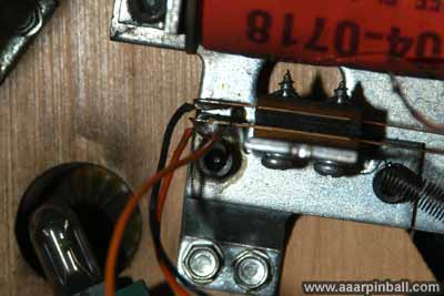
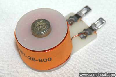
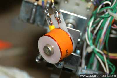
Below is the new coil that arrived in the mail. The second picture shows it soldered onto the wires but not yet installed into the drop target mechanism. The third picture shows the installed coil.
All was well, or so I thought. I turned on the pin for a test run, only to find the coil was stuck powered on! There was a noticeable constant buzzing coming from the back of the playfield. I quickly turned the machine off and checked my work. Everything looked fine. Now I understood why the original coil had failed... because it was stuck on and burnt up. Transistor Q13 on the 8 driver board runs this coil. I used the transistor check method and it stated the transistor was fine. However, after checking everything else I could think of and not finding anything wrong, I decided to replace the Q13 transistor. Keep in mind the transistor check method doesn't always catch bad transistors.
Problem solved! When I turned on the pin, no stuck coil noise. I went into diagnostics and tested the solenoid that drives the coil. "Click" when the target as it dropped down. Problem solved!
Ball Popper Mechanism
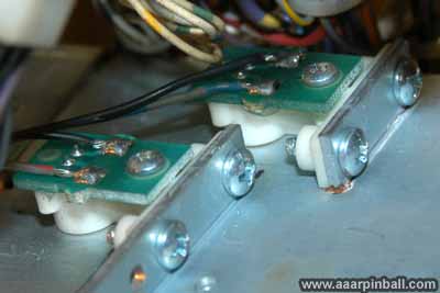
The ball popper mechanism allows a ball in the subway to pop up to the playfield. The first picture below shows the two optos on the side of the mechanism. The second picture is a close-up of the optos. These can get dirty, but they are easily unscrewed so they can be cleaned. The third picture below shows the mechanism from the opposite side.
Delta Quadrant Diverter Problem
When the ball was hit into the delta quadrant, it would always get stuck for about 2-3 seconds. After this time it would roll out slowly onto the wire ramp. It turns out the diverter wasn't adjusted correctly. When the ball is hit up the delta quadrant, the CPU often triggers a solenoid to move the diverter such that the ball does not go into the Borg ship but rather is routed to the wire ramp. When the diverter triggered, it moved too far into the pinball lane Instead for causing the ball to roll down the wire ramp, it blocked the ball! The diverter mechanism below the playfield is shown below.
A simple adjustment solved the problem. I loosened the diverter from the mechanism and adjusted it so that it caused the ball to go down the wire ramp but didn't block the path. I then tightened the mechanism. Problem solved!
Issues I haven't written up yet
-
gun handle trigger was way too tight. (fixed --- seemed to have the wrong spring installed. replaced with correct spring and feels much better)
-
Lower left popper wasn't working. (fixed --- simple switch adjustment)
Apron Decals
This pin has cool decals on the apron.
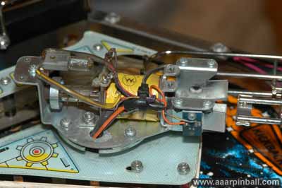
Wonder what the Borg Ship mechanism looks like?
Here is a picture...
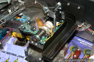
Wonder what the cannon mechanism looks like?
Here is a picture...
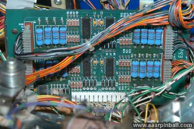
What does the opto PCB board look like?
Here is a picture...
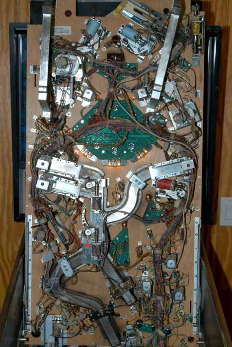
What does it look like under the playfield?
Here is a picture...