Sega Super GT Video Arcade
Repairs, Restorations, Tweaks and Insights

Introduction
6/22/2010
I enjoyed played Sega Super GT a couple of times while I was living in California's Bay Area. There was an arcade in (or connected to) a mall in Cupertino that had Super GT. I believe this was around 1997 or so.
At the time of writing this, I have owned Sega's Daytona 2 for about a year. It's a great game. My only complaint is that I cannot race against another player because I don't have a twin Daytona 2. Luck struck, however. A good deal on a Sega Super GT twin came up locally. Did I need a twin Super GT and a Daytona 2? No, probably not. However, after thinking about it for a week, I decided I would kick myself if I didn't purchase it.
Side note: I once let an Atari Star Wars go because I didn't act soon enough. That was a good deal I missed. I didn't want that to happen again.
The Super GT twin did have some problems. It was a bit more in disarray than I expected, but I decided to go ahead with the deal.
Super GT in the Basement!
6/22/2010
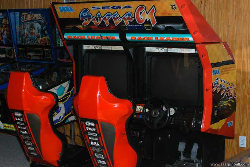
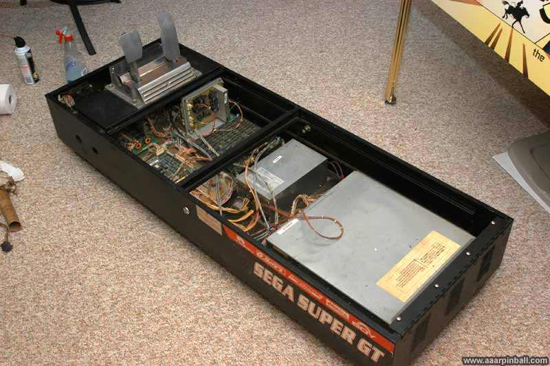
Initially placed in my garage, Super GT was taken apart, moved down the stairs to my basement, and then reassembled. Below is a picture showing the end result.
SCUD Race
SCUD Race is the same game as Super GT. Outside of the US, the game is called SCUD race. In the US, it is called Super GT. It seems the marketing people did have some input on the name. By the way, SCUD stands for Sports Car Ultimate Drive.
SuperGT Attract Mode Video (in HD)
6/9/2010
The video below, in 720p, shows the twin's attract mode.
Networked Twins!
6/22/2010
As mentioned earlier, one very cool aspect of a twin Super GT is the ability to race against another player. The two cabinets connect to each other using fiber optic tables. These are the same form factor as optical SPDIF/toslink. Each cabinet has 2 cables, one for transmit and one for receive. You need to connect the transmit of one cabinet to the receive of the other cabinet.
Connecting two male SPDIF/toslink cables together requires a male to male adaptor (called a coupler). My Super GT only came with a single coupler. I was happy to show that the networking was operational using only the one coupler and carefully holding the other two SPDIF/toslink cables together by hand. This allowed the light to pass from one to the other. Super GT will not boot past the self test screen if it is configured for networking and connectivity cannot be established. Using this hand held approach I was able to get connectivity and start a two player game (with a second person starting the game while I held the cables together).
Luckily optical SPDIF/toslink couplers are easy to find. I was able to purchase 2 of them for $2 each. I wanted a backup. These couplers are even cheaper online, but it's hard to go wrong with a local $2 purchase.
Side Art Picture?
6/9/2010
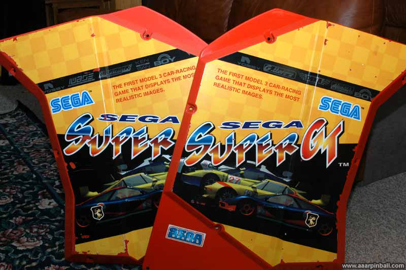
Below is an image of the left and right side art. Each side isn't in great shape, but it's pretty good considering it is from 1997!
Lots of Cracking in Audio
6/22/2010
The rear audio for both cabinets had terrible cracking. I was originally concerned that this might indicate some sort of audio driver problem, but my concern proved unwarranted when I found that the cracking completely went away if I disconnected the volume connector from the volume pot in the coin door. This, of course, made the volume play at full level, which was painful and made the game no fun.
Sega uses B5K pots, which means they are 5K Ohms and linear. I thought about switching to an audio pot, but when the local electronic store (ok, Radio Shack) only had the linear ones, that's what I got. The replacement pots have much longer shafts than the original. That is a small price to pay for getting the repair done quickly.
There are 4 pots. Two for the left cabinet and two for the right cabinet. For each cabinet, one controls the front volume and one controls the rear volume.
The pots have 3 wires attached. The repair was straightforward.
-
Loosen the screw that holds the volume knob onto the pot (sometimes harder to do than it sounds)
-
Remove the volume knob
-
Unscrew the small nut that holds the pot in place
-
Push the pot out toward the back of the coin door
-
Cut the wires from the old put (see below for ordering suggestion)
-
Strip the wires and solder onto the replacement pot.
-
Note: I typically do #5 and #6 one at a time. I cut one wire and solder it onto the new part so there is no confusion about what wire goes where
-
Push the pot back into the hole in the coin door and attach the retaining nut. Note there is a little notch that holds the pot in place.
-
Optionally put the volume knob back on --- but I didn't because it just looked silly.
A week or so after replacing the two pots that control the rear volume for each cabinet, I noticed that occasionally cracking would occur on the front speakers. I decided to replace both front pots also.
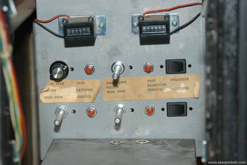
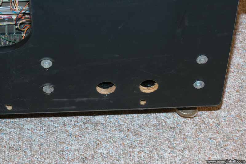
The image below shows the inside of the coin door box after 3 pots have been replaced.
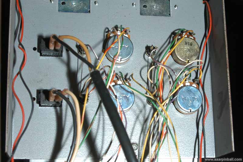
Below shows the replaced three pots from the back of the coin door. The silver ones are the new ones.
Gear Shift Broken
The gear shift for the master cabinet didn't work. It would only register one of the gears. Also, the black plastic cover that hides the inside was cracked. I didn't realize the gear shift operated so poorly until I got the game home. Luckily, however, it turned out to be repairable. When I took the gear shift apart, I found a bunch of parts in the bottom of the gear shift housing.
A rod that goes horizontally though the shifter had apparently become unscrewed and it fell out along with 4 other round parts that go along with it. I was able to put the rod back into the correct position as well as the 4 washer-like parts. Finally, a screw was in the housing that fit perfectly into the rod. Good as new! I'm sorry that I don't have any pictures of this process.
When I got the mechanism back together, I realized there was another part in the housing. It was a microswitch activator level. It had broken off one of the gear shift microswitches. This meant that, even though I got the mechanism back together, it wouldn't work.
I was surprised to find out how simple the electronics are for the gear shift. There are only 3 microswitches. If I recall, one switch indicates if the gear is left or right. Then the other two switches indicate of the gear up or down. Don't quote me on that, however.
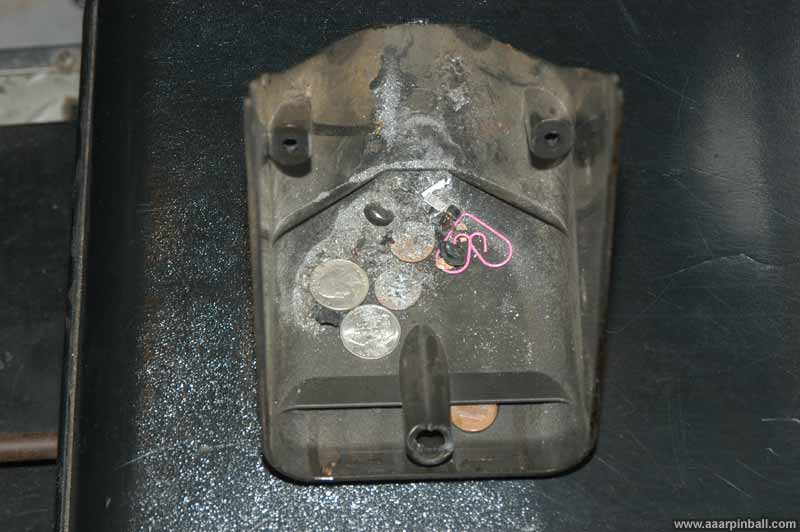
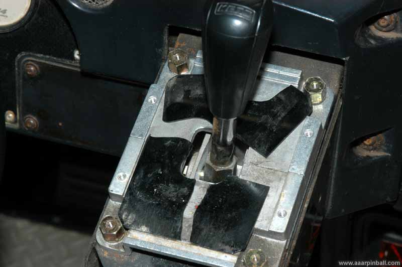
Below is an image of the gear shift with the cover removed. Looks like a few sodas were spilled on it...

The bottom housing is shown in the picture below. In addition to a ton of metal shavings, you can see some other stuff. A couple of quarters, a couple of dines, a penny, a heart shaped paperclip. This is also where the parts to the gear shift were found.
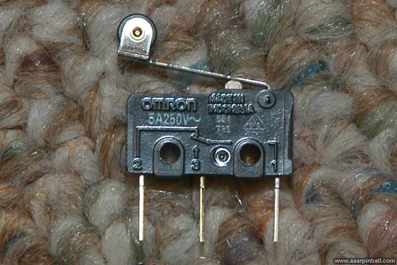
Below is a picture of a working Sega gear shift microswitch. According to the manual this is part 509-5636. It looks like a pretty standard microswitch with a couple of items to note:
1) It has a metal activator arm with a rolling wheel on the top. It is hard to see in the picture since it starts getting obstructed by the metal gear shift frame.
2) The activator arm is built into the switch. This is different than most pinball activator arms that can be removed and replaced.

The (over exposed) image below show the broken microswitch. This switch works fine except that it is missing the activator arm. I did find the activator arm in the bottom of the gear shift housing.
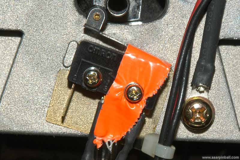
I did a quick temporary fix and connected the activator using orange duct tape. Below is an image of this hack. Of course, this was only done until I could get a replacement microswitch. This didn't work too well. See section below for the reason...
I was able to find a replacement microswitch. Sega lists the part as 509-5636 but that part is no where to be located. Fortunately, I was able to find an excellent replacement part. It is an Omrom SS-5GL2T. The image below shows what a new one looks like.
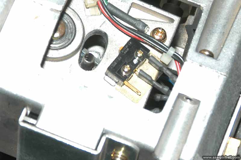
The image below shows how the replacement microswitch looks after installed. No more orange duct tape!

Yiikes! Data Access Exception!
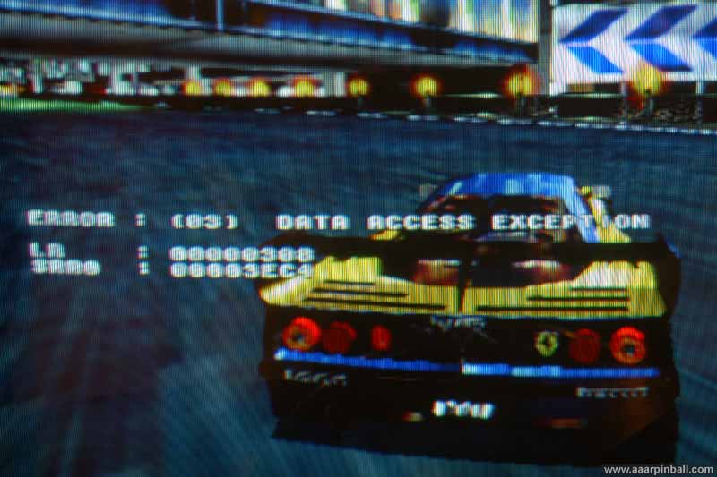
When I first did the hack repair to the gear shift microswitch, I was pretty pleased with myself since the shifter was working. Then, during the second test game, the CPU crashed! It displayed
ERROR : (03) DATA ACCESS EXCEPTION
LR : 00000308
SRR0 : 00003EC4
When this crash occurred, the background music kept playing but nothing else worked. A power cycle was required to recover. I played a few more games and the data access exception kept occurring. One time the screen went completely wacky shortly after the exception, but all other times it looked as shown in the picture below.
I thought, "how could I possibly have caused this?" I played some additional games and proved the data access exception only occurred when I shifted gears. It did not, however, occur each and every time I shifted gears. After some additional investigation, I found that I could reproduce this exception 100% of the time if I manually activated both the left microswitch and the right microswitch at the same time.
Looking at the gear shift mechanism, you can see both switches should never be active at the same time. My hack fix to the broken microswitch activator (described above) appeared to sometimes not allow the microswitch to deactivate quickly. As a result, sometimes the left microswitch would be activated before my hacked right one released. Wham! Sega Super GT CRASH!
I'm a bit surprised our friends at Sega released the code this way. I seriously doubt the software couldn't handle this situation. I would think they would rather allow the game to be played, even with a broken or messed up gear shift, than to cause the CPU to crash. Just my 2 cents.
Even more Data Access Exception
6/6/2010
The crash came back several games after the hack repair was removed and the real repair was done. I dug into it some more and found out that the left microswitch was sticky. Perhaps it wasn't my hack repair, but the left microswitch all along? Some times when I activated the left microswitch with my finger, I could watch it release slowly. The other microswitches, especially the new one I just installed, released immediately.
I sprayed a small amount of contact cleaner into the switch. It did wonders. The switch pops up immediately now. Problem now seems completely fixed. Crossing my fingers :)
How does the Gear Shift work?
6/6/2010
The Sega racer gear shifts have 3 microswitches. As you are looking at the gear shift (from the players perspective) there is a left, right and top gear shift. The table below shows how the switches are activated for each of the 4 gears.
| Left Microswitch | Top Microswitch | Right Microswitch | |
| Gear 1 | Not active | Active | Active |
| Gear 2 | Active | Active | Not active |
| Gear 3 | Not active | Not active | Active |
| Gear 4 | Active | Not active | Not active |
From the table above, it seems fair to name the 3 microswitches as follows
-
Left microwitch can be called "Down"
-
Top microswitch can be called "Left"
-
Right microswitch can be called "Up"
Gear Shift Plate
6/9/2010
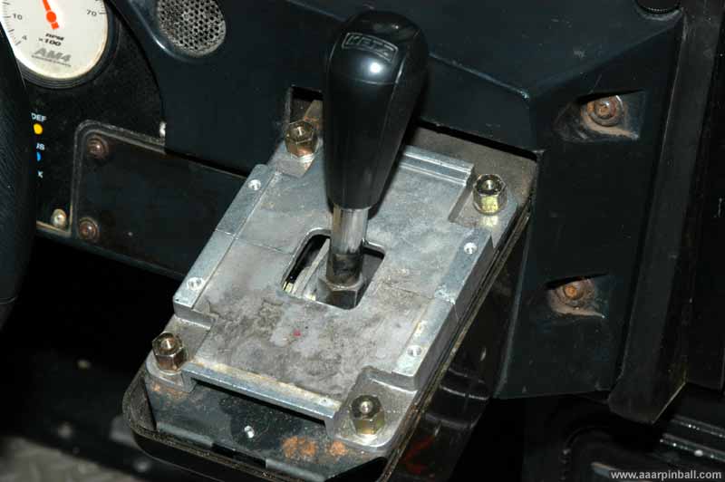
While it is purely cosmetic, the gear shift plate was broken. This is the thin plastic-like material that slides around with the gear shift and hides the opening. A picture is shown below.
Below is a picture showing the hole that is covered by the plate, with the broken plate removed.
I ordered a new plate, one that was for Daytona. I assumed (guessed?) it would work with SuperGT. It turns out that it's too tall. I used a dremel-like tool and cut it to size.
Poor Steering
6/9/2010
When SuperGT first arrived, the left cabinet had a broken gear shift. Since I like to use manual, rather than automatic, my initial testing (and playing) was done on the right cabinet. The first couple of games I played left me asking, "what the heck is up with these controls?" Although I was no SuperGT expert back in the day, I didn't recall the control being so difficult.
I went into the diags and tested out the steering. The game reads, more or less, from 0x20 to 0xE0 with 0x80 being "center". I quickly learned that the readings were wacky. While I would get around a 0x80 with the wheel centered, turning the wheel to the left caused unexpected results. It would start counting down and then, all of a sudden, go up to 0xA0 and count up! At that point I understood why the control seemed so bizarre ... when turning to the left, the game would think I was turning to the right for a bit. If I kept turning left, the readings would eventually come back into line. However, at full left turn, it started reading as a far right turn.
The good news was that the repair seemed pretty straightforward. A potentiometer (aka "volume") needed to be replaced. This is a 5KOhm potentiometer that costs about $20. Not too expensive from my pin background, but pretty painful when similar parts are often just $2. The steering wheel panel must be removed from the game in order to perform this repair. That's easy, just 4 security screws and 2 bolts.
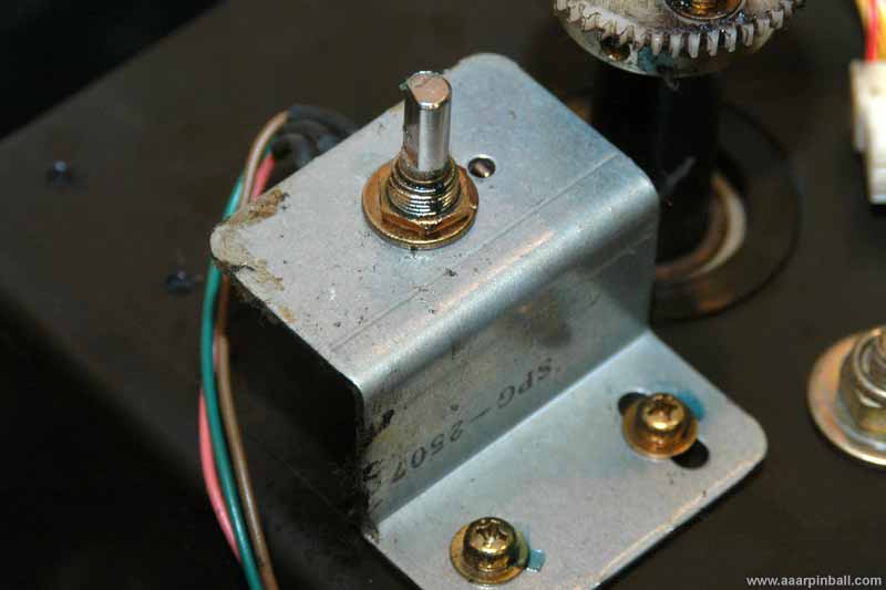
The potentiometer mechanism is pretty straightforward. A gear is screwed onto a mounting plate. This mounting plate is then tightened onto the potentiometer's shaft. The image below shows the original potentiometer and the mounting plate. I have already taken the gear off.
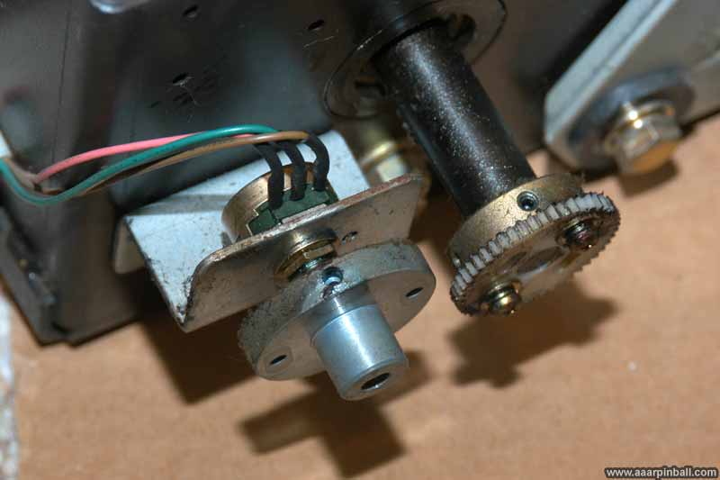
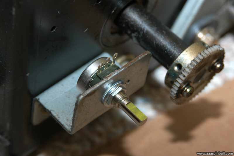
The mounting plate is secured onto the potentiometer's shaft using 2 small hex screws. These are metric and a 1.5 hex key is required. The image below shows the mounting plate removed, exposing the original potentiometer's shaft.
The potentiometer is removed by loosening the hex nut. The 3 wires going to the potentiometer were soldered, so I needed to cut them off. The newly installed potentiometer is shown in the picture below.
While I don't have any pictures of the final repair, it simply involved soldering the 3 wires to the new potentiometer, attaching the mounting plate to the shaft, and attaching the gear to the mounting plate. When I attached the gear, I made sure the steering wheel was completely centered and made sure the potentiometer's shaft was rotated to it's middle position.
When everything was put back together, the diagnostics showed the hex number increasing and decreasing smoothly as I turned the steering wheel. Also, when the wheel was dead center, the diags reported 0x81. That's pretty close to the perfect value of 0x80.
Power Cord was Cut!
I wonder if it was an accident or someone was just in a hurry and didn't want to deal with unplugging the game? How hard could that have been? I guess I'll never know. Either way, my Super GT has a power cord that is about 8 inches long and doesn't have the plug at the end! You can see it below.
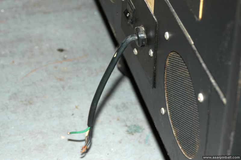
The picture below shows how the cord goes through the strain protector and connects to the power switch.
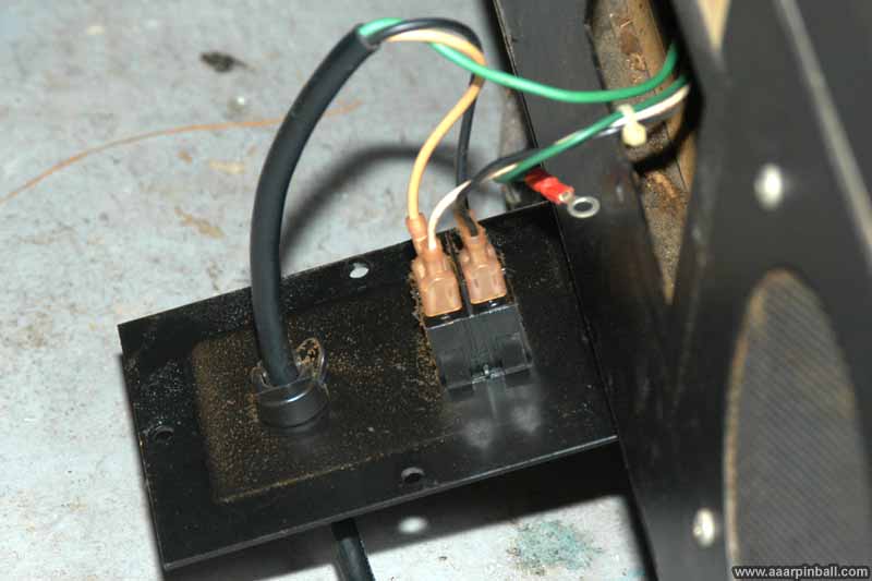
I replaced the cord. I used pliers to get the strain relief piece off and then I put a new cord though it. Then, using pliers again, I put the strain relief piece (now with the cord though it) back onto the metal back plate. Good as new!
Low Cabinet Serial Number
6/9/2010
I'm sure it makes absolutely no difference, but it's a nice conversation piece that one of the cabinets states it is serial number 35. See the picture below. It's also slightly interesting that someone wrote "Grand" by hand on the sticker. Instead of a "Super Car - L", I have a "Grand Super Car - L". :)
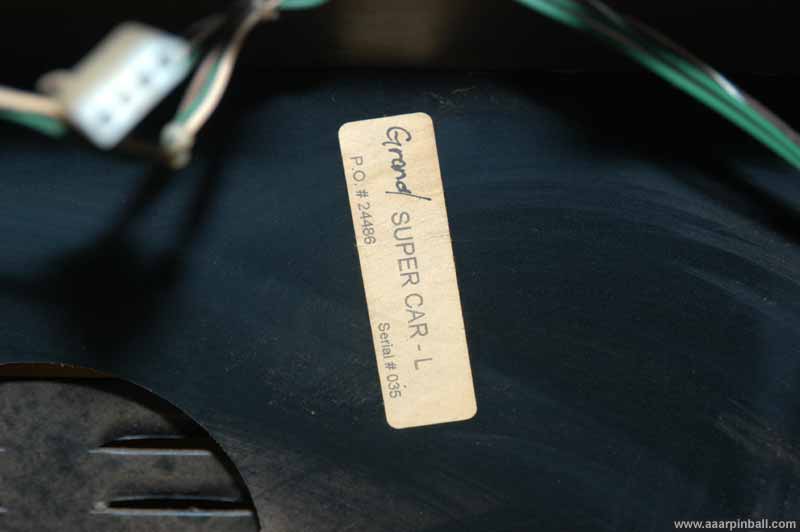
I suspect the "Super Car" comes from the non-US name of the game, Super Car Ultimate Drive. I guess that the "dash L" means the left cabinet since the right cabinet says "Grand Super Car - R". The serial number for the right cabinet is much higher (300+). Also, the "grand" part isn't written by hand.
Super GT cabinet differences from Daytona 2
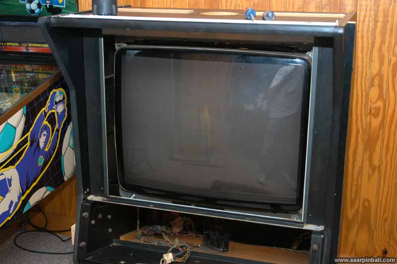
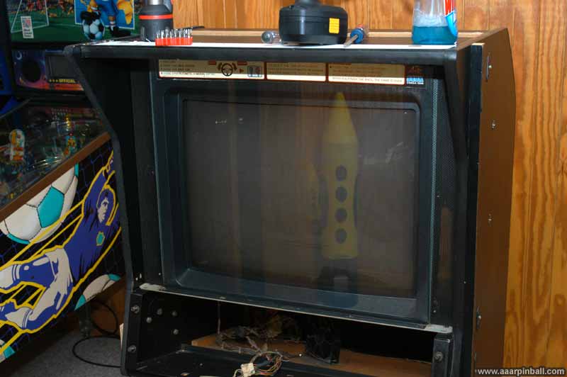
I knew that the Daytona 2 cabinet was different than the Super GT cabinet, but I didn't expect the difference to cause the process of taking about the Super GT cabinet to be so different. The monitor cabinet is different different between the two. The Daytona 2 cabinet has metal rails that support the monitor cabinet while the Super GT cabinet has wide wooden supports. For example, when viewed from the side, you can see a player's shoes with the Daytona 2 cabinet while you cannot with the Super GT cabinet.
What I didn't know, however, is that the Super GT monitor cabinet is permanently attached to the support structure while the Daytona 2 isn't. If you look back at my Daytona 2 section, I was able to take the Daytona 2 monitor cabinet off the support structure. The support structure remained attached to the "little wing" base. However, in the case of Super GT, the support structure and the monitor cabinet must be removed from the "little wing" (or "Sega Super GT") base.
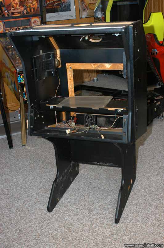
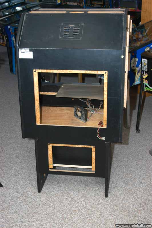
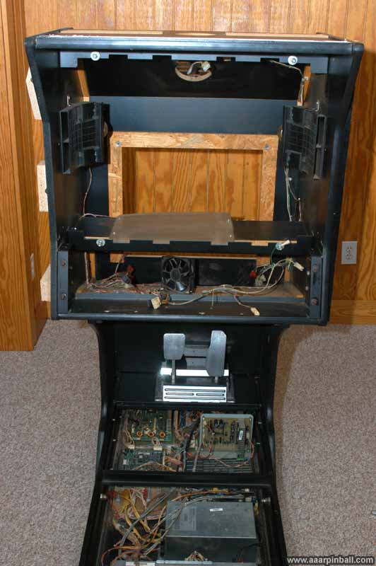
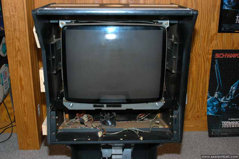
The picture below shows the single unit comprising the monitor case and the support structure. The first picture is the front and the second is the back.
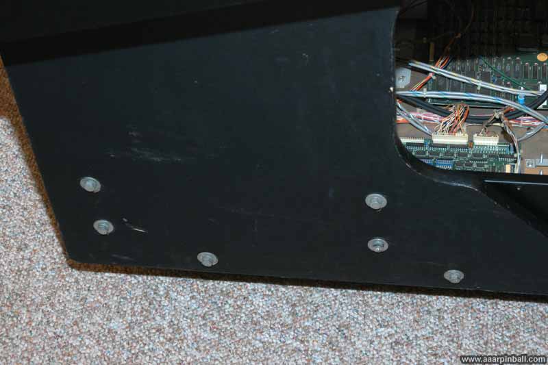
The monitor support structure is connected to the "Sega Super GT" base by 10 bolts. I don't know if this is the standard configuration, but when I received my Super GT there were 6 bolts on the outside of the cabinet and 4 bolts on the inside. When I say "outside" I meant the side that doesn't touch the other twin cabinet. When I say "inside" I mean the side that does touch the other twin cabinet. The outside is picture below, immediately followed by an image of the inside.
Below is an image of the "Sega Super GT" support body without the monitor cabinet and supports attached.
Steps to Take SuperGT Apart
6/16/2010
Informal steps to take apart the Super GT. This is from memory. If something doesn't look right, it may very well not be correct. Ping me if I can help.
-
Remove the huge topper
-
Separate the two cabs. The coin door box is most likely bolted to both. Also, there is some support plate that holds them together (although mine didn't have it, so I cannot say much about)
-
Disconnect all the coin door wires and network cables
-
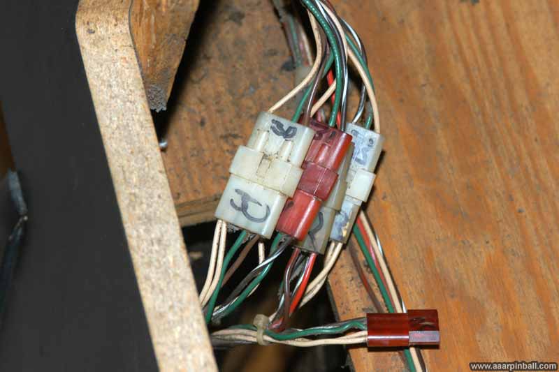
Open the back monitor cover and label all the connectors. There is a group on the left side, a group on the right side, and a few going to the control panel.
-
Open the bottom cover (above the power supply) and remove the three connections.
-
Look closely at the wires. You will need to remove any "loop" tie downs that connect them to the cabinet. When you disconnect the monitor cabinet from the base, these cables need to not be attached to the monitor cabinet. I think there are 4 or so of these that need to be removed.
-
Disconnect the monitor connectors
-
Remove the control panel (with the steering wheel). There are 4 security screws on the front and then two bolts below the control panel.
-
Before you can remove the control panel, there are two triangle like metal pieces on the top left and right of the control panel. You need to unscrew the front most screw from each. This allows the piece to tilt. Doing this makes it easier to remove the control panel.
-
I've found having the chair still attached at this point is useful. Sit in the chair and, after making sure you have disconnected all the correct cables, remove the control panel. I've found you need to tilt the front upwards a little bit. It's heavy! No joke,
-
Remove the front monitor frame. This takes some work. Just start remove the visible screws.
-
Once you get the glass removed, you will need to use a flexible screwdriver extender (I use one for a drill) and unscrew 3 long screws on each side of the cabinet. These screws are on the inside of the monitor frame, just behind the mesh. This is the biggest pain.
-
Now you need to remove the monitor. There are 4 nuts that hold it in place. These are the outermost nuts.
-
Before pulling out the monitor, make sure you are ok with this. You should look up monitor safety and perhaps discharge the monitor. Proceeded at your own risk!
-
After you have read about monitor safety and know what you are doing, make sure you have all the monitor cables disconnected. Assuming you do, you should be able to pull the monitor straight out. It's also very heavy! Be careful not to drop it and be safe.
-
Time to remove the monitor cabinet from the metal base. You should have a helper. At a minimum put 2 2x4 boards under the front-most part of the monitor cabinet. This will help support the front of the cabinet when you remove the screws. The back is already resting on a solid portion.
-
Remove the various bolts from the left and right of the monitor cabinet. On mine there were 6 on the outside and 4 on the inside.
-
Note: there is a metal plate that I'm not sure if you need to remove. I did, but in retrospect, I don't know if it was needed. Looking through the door just above the power supply, there rare 3 hex screws holding a metal plate in position. I removed this plate. Again, not sure if it's necessary.
-
With all the bolts removed, and after doubt checking you disconnected all the connectors and don't have anything tied into the cabinet, lift the monitor cabinet off the base. If the chair is on the left and the accelerator/break is on the right, all you need to do is lift the monitor cabinet an inch or so and the side it a few inches to the right. Set it down on the ground. Then you can roll the metal base out from it.
-
Now you need to remove the chair from the metal base. First, tilt up the chair and disconnect the speaker cable.
-
The chair is held on the metal base by 5 or so security screws on a hinge. Just remove them all and lift off the chair.
-
You should have the following separate components: chair, metal base, wooden monitor cabinet, monitor.
-
Each is pretty heavy by itself, so get help moving them!
Picture of monitor cabinet and support attached to base.
One set of connectors shown below.
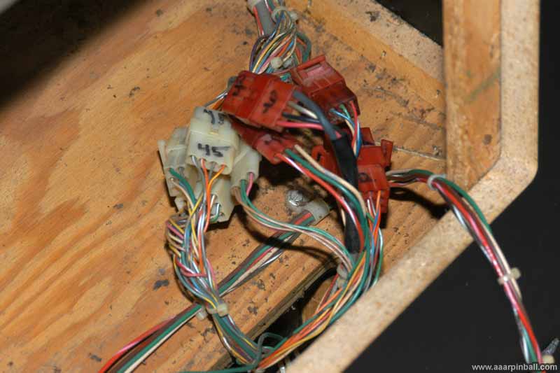
A second set of connectors shown below.
The monitor has been put back into the monitor cabinet.
The support frame as been placed in front of the monitor.
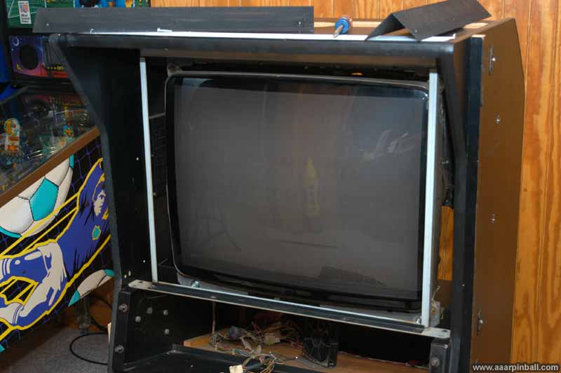
The plastic monitor bevel has been added.
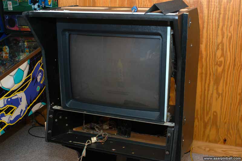
The black metal speaker mesh has been added to each side of the monitor.
The monitor glass has been installed.
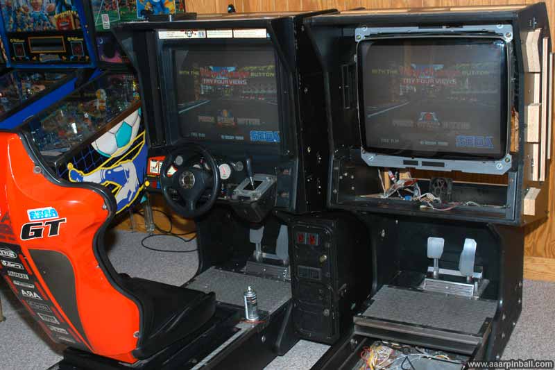
Below is a picture of the twins after taking apart the right cabinet, bringing it into the basement, and putting it mostly back together.
Monitor Condition
... talk about ....
Topper Cut Cable
6/18/2010
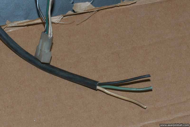
Just like the power cable, one of the 4 cables going to the topper was cut. It was the power cable to the leftmost florescent light.. Luckily, it was easy to determine what the appropriate connector should be because the other end was present as well as the same cable for the other cabinet. It was a standard male 0.093 molex connector. Below is a picture of the cut cable.
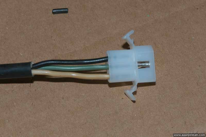
I crimped the 3 male pins onto the cable and inserted them into the housing. Perfect repair. The end result is shown below.
Topper Lighting
6/18/2010
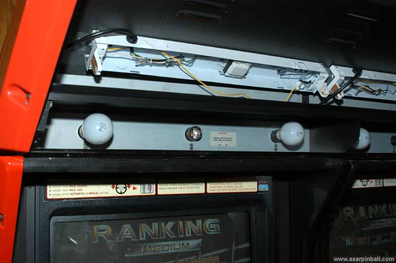
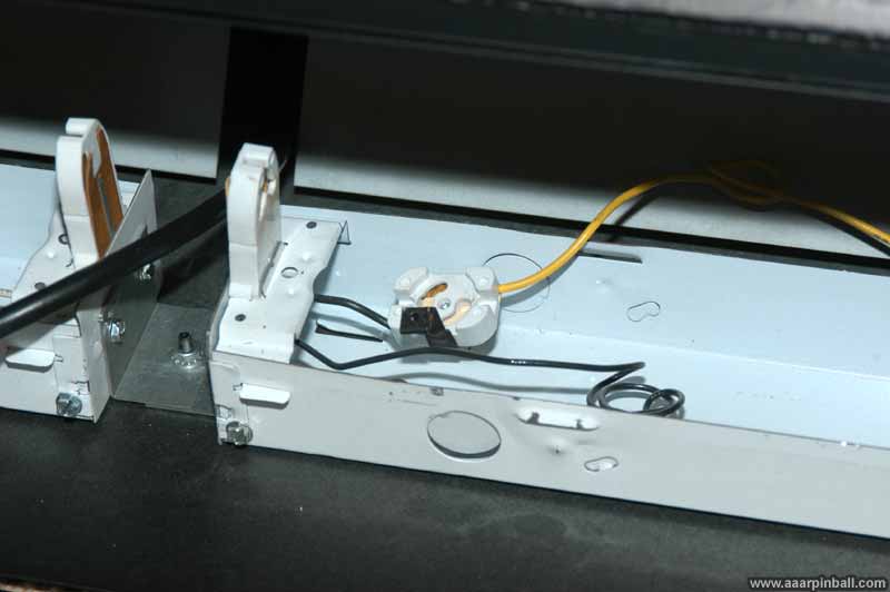
The topper has lighting in 3 areas: translite, left race leader, and right racer leader. The translite lighting is achieved by 2 fluorescent lights. The race leaders surprised me. They are illuminated by 3 regular 25 watt bulbs. These are the "A19" bulbs used in most home lights, although a lower wattage. An image of the leftmost fluorescent and race leader lights is shown below. Yes, I know that all the bulbs are not installed :)
Not only did a previous owner of my Super GT remove the fluorescent lights, but they also removed the starters. This is shown below.
It turns out that a FS2 starter works perfectly. Also, a 24" 20 watt fluorescent light works perfectly.
Right Cabinet Race Leader always Illuminated
6/25/2010
After getting all the topper lighting wired up, I found out that the right cabinet's "Race Leader" was always on. Each cabinet has a "Race Leader" sign which lights up when the player using that specific cabinet is in the lead. It does an excellent job of making spectators feel more involved in the race. That is, when it is working.
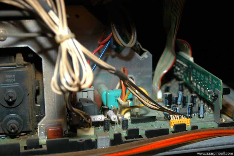
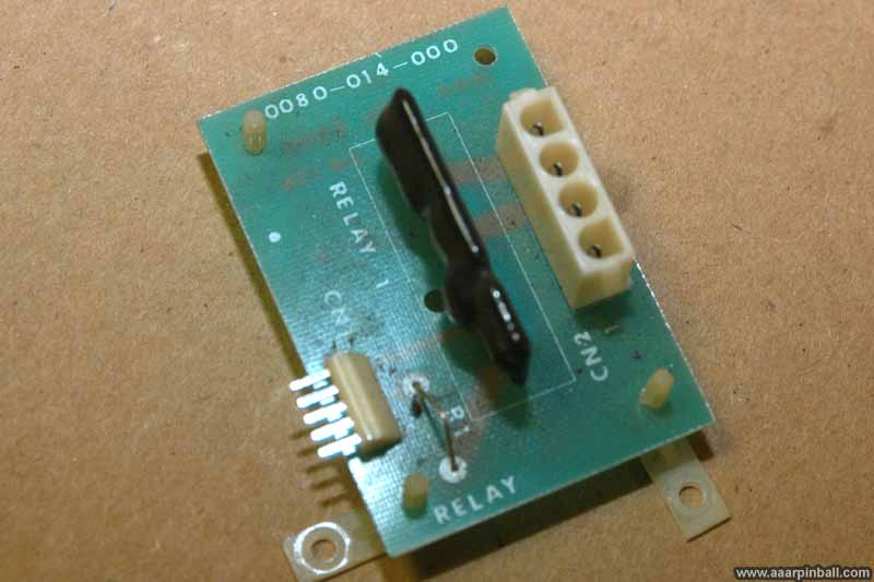
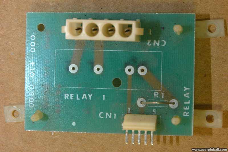
Sega must have expected this problem to occur because the relay that controls the "Race Leader" light is on a separate board. I believe Sega expected the operator to replace the entire board. This board has two input connectors. The smaller input connector comes from the CPU cage and tells the relay when to activate. The larger connector is 120V AC. This contains power from the wall as well as a circuit running to the "Race Leader" lights. When the relay is active, it allows the 120V current to flow on the "Race Leader" circuit, thus turning on the light. Below is a picture of the board with the original relay. This board/PCB ID is Sega 0080-014-0000.
Before I removed the relay board, I verified that the control voltage was working. When a DMM I could easily see that the control voltage did change from 0V to 5V when the game wanted to enable the "Race Leader" light. This was good news because it indicated there wasn't anything wrong with the driving transistor and strongly pointed toward the relay.
When I removed the board, I tested the relay. The two pins for the load circuit, the ones that open and close the "Race Leader" circuit, were closed. This indicated that the relay was bad since a solid state relay shouldn't have a closed load circuit as the default configuration. This explained why the "Race Leader" was always turned on.
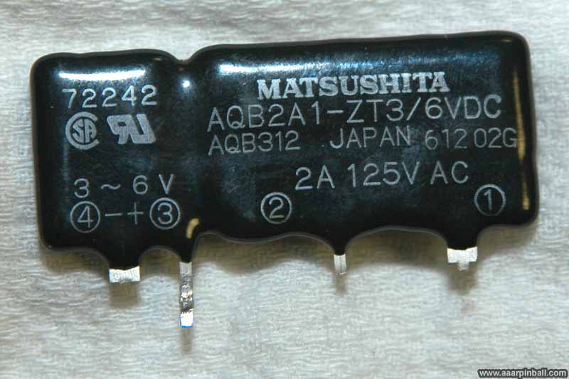
The original relay on the board is a Matsushita part # AQB2A1-ZT3. This part states it has a control voltage between 3v and 6 volts. This means that passing between 3v and 6v on the control circuit will close the load circuit. The load circuit is rated 2A at 125V AC. This is a solid state relay (opposed to a mechanical relay). A picture of the part is below.
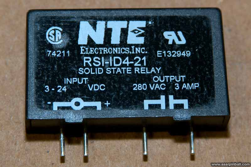
When looking for a suitable replacement for the bad relay, I came across a site discussing the relay for Sega's After Burner (http://dweeb.net/afterburner/). It pointed me to a NTE part # RSI-ID4-21. It seems Sega has been putting this type of relay on a separate board for a while. The NTE part has better specifications for the load circuit than the original part. It allows up to 3A at 280 VAC. It also happens to support a wider control voltage, but this doesn't provide any benefit.
I ordered this NTE relay to replace the bad original relay. A picture is included below.
I desoldered the bad relay from the board. The result is shown below.
Only two steps left. First, solder the new NTE replacement relay onto the board. Second, reinstall the board into the Super GT cabinet and cross fingers that the problem is fixed. The picture show the newly soldered part. The NTE relay fits perfectly and the repair turned out nice. It's worth noting that unlike the case of the Sega After Burner repair mentioned on the dweeb.net site, the NTE fit perfectly and didn't require any minor bending of the pins to fit in the Super GT 0080-014-000 board.
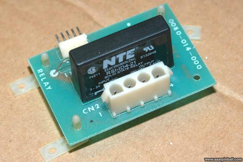
I powered on the Super GT, waited for it to go into attract mode and ... drum roll... it worked! The right cabinet "Race Leader" was not always on. Furthermore, it flashed in synchronicity with the left cabinet from time to time. Sometimes it flashed immediately before or immediately after the left cabinet, creating a nice effect. Finally, going into the diagnostics, the right cabinet's "Race Leader" light turned on (and off) as indicated by the cycling test.
Cleaning the Chairs
6/18/2010
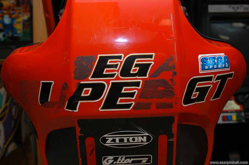
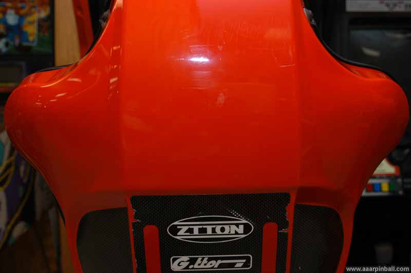
The SuperGT chairs have stickers on the back. The top most set of stickers says "Sega" and the stickers below that say "Super GT". At least in the case of my SuperGT, there is also a single "Sega Sports" sticker to the right of the "Sega". Unfortunately, theses stickers were not in the greatest of shape. See for yourself in the picture below.
Since my Daytona 2 has no stickers on the top portion of the chair, I figured the best solution to this problem was to remove the stickers all together. Using Goo Gone, a plastic credit card, and a lot of elbow grease, the stickers started coming off. The picture below shows the operation in progress.
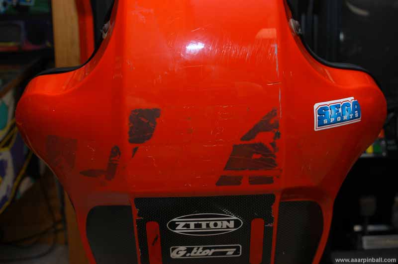
After some more work, the final result is shown below. It looks great. It really looks much better in person. The JPEG compression does not help either. As you can see, I left the larger sticker with the brand names. This sticker is generally in good shape and add character to the cabinet.
Questionable Translation?
I laughed a bit when I saw the side of the Super GT cabinet prominently states the following: "The first model 3 car-racing game that displays the most realistic images." Wow. That's certainly not the best translation from Japanese to English. It also confuses people that don't know what a "model 3" is and attempt to associate the "3" with car... Where were the US based sale people? :)